

338
Practical MATLAB
® Applications for Engineers
has a gain of k, where k and K are constants, and in general K ≠ k (in passive systems k > K).
R.4.63 Strictly speaking the process of distortion occurs if the output y(t) of a system is not
its input scaled by a constant, and its phase is not linear with respect to w.
R.4.64 If the phase shift associated with its output is not linear with respect to w, the
various input frequencies will appear at the output with different time delays,
creating what is referred to as delay distortion. Most electronic devices introduce
both amplitude and delay distortion to same degree. The amount of distortion that
can be tolerated by a device depends on the application.
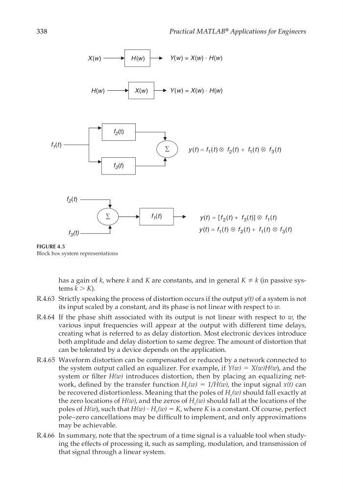
R.4.65 Waveform distortion can be compensated or reduced by a network connected to
the system output called an equalizer. For example, if Y(w) = X(w)H(w), and the
system or fi lter H(w) introduces distortion, then by placing an equalizing network, defi ned by the transfer function H e (w) = 1/H(w), the input signal x(t) can
be recovered distortionless. Meaning that the poles of H e (w) should fall exactly at
the zero locations of H(w), and the zeros of H e (w) should fall at the locations of the
poles of H(w), such that H(w) ⋅ H e (w) = K, where K is a constant. Of course, perfect
pole–zero cancellations may be diffi cult to implement, and only approximations
may be achievable.
R.4.66 In summary, note that the spectrum of a time signal is a valuable tool when studying the effects of processing it, such as sampling, modulation, and transmission of
that signal through a linear system.
X(w)
Y(w ) = X(w) . H(w)
H(w)
Y(w) = X(w) . H(w)
f 1 (t)
f 1 (t)
f 2 (t)
f 3 (t)
H (w)
X(w)
f 2 (t)
f 3 (t)
)
(
)
(
)
(
)
(
)
(
3
1
2
1
t
f
t
f
t
f
t
f
t
y
⊗
+
⊗
=
)
(
)]
(
)
(
[
)
(
1
3
2
t
f
t
f
t
f
t
y
⊗
+
=
)
(
)
(
)
(
)
(
)
(
3
1
2
1
t
f
t
f
t
f
t
f
t
y
⊗
+
⊗
=
FIGURE 4.5
Block box system representations
CRC_47760_CH004.indd 338
CRC_47760_CH004.indd 338
7/28/2008 12:25:55 PM
7/28/2008 12:25:55 PM
Practical MATLAB
® Applications for Engineers
has a gain of k, where k and K are constants, and in general K ≠ k (in passive systems k > K).
R.4.63 Strictly speaking the process of distortion occurs if the output y(t) of a system is not
its input scaled by a constant, and its phase is not linear with respect to w.
R.4.64 If the phase shift associated with its output is not linear with respect to w, the
various input frequencies will appear at the output with different time delays,
creating what is referred to as delay distortion. Most electronic devices introduce
both amplitude and delay distortion to same degree. The amount of distortion that
can be tolerated by a device depends on the application.
R.4.65 Waveform distortion can be compensated or reduced by a network connected to
the system output called an equalizer. For example, if Y(w) = X(w)H(w), and the
system or fi lter H(w) introduces distortion, then by placing an equalizing network, defi ned by the transfer function H e (w) = 1/H(w), the input signal x(t) can
be recovered distortionless. Meaning that the poles of H e (w) should fall exactly at
the zero locations of H(w), and the zeros of H e (w) should fall at the locations of the
poles of H(w), such that H(w) ⋅ H e (w) = K, where K is a constant. Of course, perfect
pole–zero cancellations may be diffi cult to implement, and only approximations
may be achievable.
R.4.66 In summary, note that the spectrum of a time signal is a valuable tool when studying the effects of processing it, such as sampling, modulation, and transmission of
that signal through a linear system.
X(w)
Y(w ) = X(w) . H(w)
H(w)
Y(w) = X(w) . H(w)
f 1 (t)
f 1 (t)
f 2 (t)
f 3 (t)
H (w)
X(w)
f 2 (t)
f 3 (t)
)
(
)
(
)
(
)
(
)
(
3
1
2
1
t
f
t
f
t
f
t
f
t
y
⊗
+
⊗
=
)
(
)]
(
)
(
[
)
(
1
3
2
t
f
t
f
t
f
t
y
⊗
+
=
)
(
)
(
)
(
)
(
)
(
3
1
2
1
t
f
t
f
t
f
t
f
t
y
⊗
+
⊗
=
FIGURE 4.5
Block box system representations
CRC_47760_CH004.indd 338
CRC_47760_CH004.indd 338
7/28/2008 12:25:55 PM
7/28/2008 12:25:55 PM