

254
Practical MATLAB
® Applications for Engineers
and
Z
j
j
j
j
j
j
TH ϭ ϩ ϩ
ϩ
Ϫ
ϩ ϩ Ϫ
ϭ ϩ
1 4
8
4 8
4
8
4 8
4
6
4
(
)(
)
(by replacing the voltage sources by shorts).
The Thevenin’s equivalent circuit is shown in Figure 3.27.
Then,
I
V
Z
Z
j
j
L
TH
L
T H
ϭ
ϩ
ϭ
Ϫ ϩ ϭ Ϫ ϩ
10
5
10
1
05 . A
R.3.62 Note that source transformation concept for the DC case discussed in Chapter 2
can be extended to include the AC. Note that source transformation was already
employed in the example presented in R.3.61. Observe that a current source of
I = 6 + j3 with a parallel impedance of Z 2 = 8 − j4 was converted into a voltage
source of 60 V (Z 2 * I) in series with Z 2 (Figure 3.25).
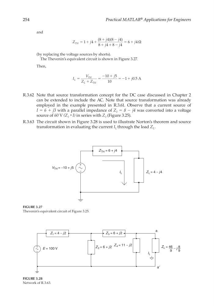
R.3.63 The circuit shown in Figure 3.28 is used to illustrate Norton’s theorem and source
transformation in evaluating the current I L through the load Z L .
V TH = −10 + j 5
Z TH = 6 + j 4
Z L = 4 − j 4
I L
FIGURE 3.27
Thevenin’s equivalent circuit of Figure 3.25.
Z 1 = 4 − j 2
Z 2 = 6 + j 2
Z 4 = 11 − j 2
Z 3 = 6 + j 2
E = 100 V
Z L = 46
a
a′
I L
9
8
9
− j
FIGURE 3.28
Network of R.3.63.
CRC_47760_CH003.indd 254
CRC_47760_CH003.indd 254
7/23/2008 1:27:38 PM
7/23/2008 1:27:38 PM
Practical MATLAB
® Applications for Engineers
and
Z
j
j
j
j
j
j
TH ϭ ϩ ϩ
ϩ
Ϫ
ϩ ϩ Ϫ
ϭ ϩ
1 4
8
4 8
4
8
4 8
4
6
4
(
)(
)
(by replacing the voltage sources by shorts).
The Thevenin’s equivalent circuit is shown in Figure 3.27.
Then,
I
V
Z
Z
j
j
L
TH
L
T H
ϭ
ϩ
ϭ
Ϫ ϩ ϭ Ϫ ϩ
10
5
10
1
05 . A
R.3.62 Note that source transformation concept for the DC case discussed in Chapter 2
can be extended to include the AC. Note that source transformation was already
employed in the example presented in R.3.61. Observe that a current source of
I = 6 + j3 with a parallel impedance of Z 2 = 8 − j4 was converted into a voltage
source of 60 V (Z 2 * I) in series with Z 2 (Figure 3.25).
R.3.63 The circuit shown in Figure 3.28 is used to illustrate Norton’s theorem and source
transformation in evaluating the current I L through the load Z L .
V TH = −10 + j 5
Z TH = 6 + j 4
Z L = 4 − j 4
I L
FIGURE 3.27
Thevenin’s equivalent circuit of Figure 3.25.
Z 1 = 4 − j 2
Z 2 = 6 + j 2
Z 4 = 11 − j 2
Z 3 = 6 + j 2
E = 100 V
Z L = 46
a
a′
I L
9
8
9
− j
FIGURE 3.28
Network of R.3.63.
CRC_47760_CH003.indd 254
CRC_47760_CH003.indd 254
7/23/2008 1:27:38 PM
7/23/2008 1:27:38 PM