

Alternating Current Analysis
253
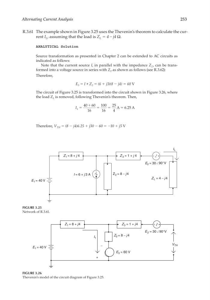
R.3.61 The example shown in Figure 3.25 uses the Thevenin’s theorem to calculate the current I L , assuming that the load is Z L = 4 – j4 Ω.
ANALYTICAL Solution
Source transformation as presented in Chapter 2 can be extended to AC circuits as
indicated as follows:
Note that the current source I, in parallel with the impedance Z 2 , can be transformed into a voltage source in series with Z 2 as shown as follows (see R.3.62):
Therefore,
E 3 = I * Z 2 = (6 + j3)(8 − j4) = 60 V
The circuit of Figure 3.25 is transformed into the circuit shown in Figure 3.26, where
the load Z L is removed, following Thevenin’s theorem. Then,
I 1
40 60
16
100
16
25
4
6 25
ϭ
ϩ ϭ
ϭ
ϭ
A
A
.
Therefore, V TH = (8 − j4)6.25 + j30 − 60 = −10 + j5 V
E 1 = 40 V
I = 6 + j 3 A
Z 1 = 8 + j 4
Z 2 = 8 − j 4
Z 3 = 1 + j 4
E 2 = 30 90°V
Z L = 4 − j 4
I L
FIGURE 3.25
Network of R.3.61.
E 1 = 40 V
E 2 = 30
Z 1 = 8 + j4
Z 2 = 8 − j 4
Z 3 = 1 + j 4
90°V
V TH
I 1
−
+
E 3 = 60 V
FIGURE 3.26
Thevenin’s model of the circuit diagram of Figure 3.25.
CRC_47760_CH003.indd 253
CRC_47760_CH003.indd 253
7/23/2008 1:27:38 PM
7/23/2008 1:27:38 PM
253
R.3.61 The example shown in Figure 3.25 uses the Thevenin’s theorem to calculate the current I L , assuming that the load is Z L = 4 – j4 Ω.
ANALYTICAL Solution
Source transformation as presented in Chapter 2 can be extended to AC circuits as
indicated as follows:
Note that the current source I, in parallel with the impedance Z 2 , can be transformed into a voltage source in series with Z 2 as shown as follows (see R.3.62):
Therefore,
E 3 = I * Z 2 = (6 + j3)(8 − j4) = 60 V
The circuit of Figure 3.25 is transformed into the circuit shown in Figure 3.26, where
the load Z L is removed, following Thevenin’s theorem. Then,
I 1
40 60
16
100
16
25
4
6 25
ϭ
ϩ ϭ
ϭ
ϭ
A
A
.
Therefore, V TH = (8 − j4)6.25 + j30 − 60 = −10 + j5 V
E 1 = 40 V
I = 6 + j 3 A
Z 1 = 8 + j 4
Z 2 = 8 − j 4
Z 3 = 1 + j 4
E 2 = 30 90°V
Z L = 4 − j 4
I L
FIGURE 3.25
Network of R.3.61.
E 1 = 40 V
E 2 = 30
Z 1 = 8 + j4
Z 2 = 8 − j 4
Z 3 = 1 + j 4
90°V
V TH
I 1
−
+
E 3 = 60 V
FIGURE 3.26
Thevenin’s model of the circuit diagram of Figure 3.25.
CRC_47760_CH003.indd 253
CRC_47760_CH003.indd 253
7/23/2008 1:27:38 PM
7/23/2008 1:27:38 PM