

Alternating Current Analysis
247
and
2
2
2
2
1
2
1
2
1
2
1
1
4
ϭ
ϩ
ϩ
ϭ
ϩ
R
RC
RC
C R
R
C
L
ϩ
The BW is then given by
BW
RC
Q
R
P
ϭ
Ϫ ϭ
ϭ
2
1
1
2
1
R.3.54 A parallel RLC circuit presents the following characteristics at resonance:
a. Z T is at a maximum.
b. Z T = R, since the angle between I and V is zero.
c. Current is at a minimum.
d. The effective power is at its minimum.
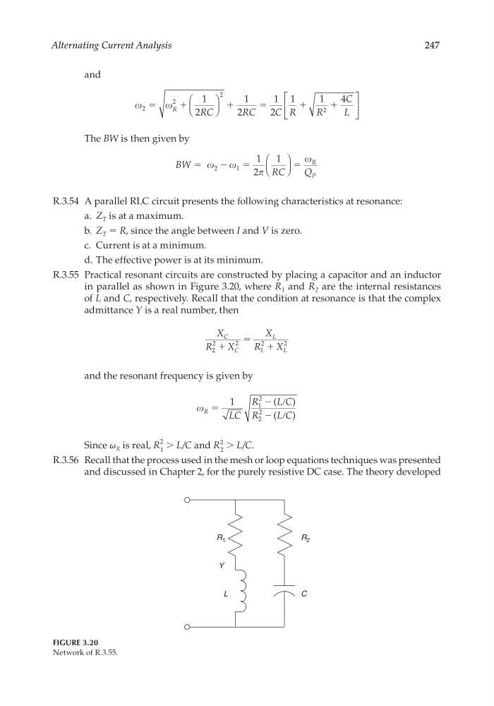
R.3.55 Practical resonant circuits are constructed by placing a capacitor and an inductor
in parallel as shown in Figure 3.20, where R 1 and R 2 are the internal resistances
of L and C, respectively. Recall that the condition at resonance is that the complex
admittance Y is a real number, then
X
R
X
X
R
X
C
C
L
L
2
2
2
1
2
2
ϩ
ϭ
ϩ
and the resonant frequency is given by
R
LC
R
L C
R
L C
ϭ
Ϫ ր
Ϫ ր
1
1
2
2
2
(
)
(
)
Since ω R is real, R
2
1
> L/C and R
2
2
> L/C.
R.3.56 Recall that the process used in the mesh or loop equations techniques was presented
and discussed in Chapter 2, for the purely resistive DC case. The theory developed
C
L
R 2
R 1
Y
FIGURE 3.20
Network of R.3.55.
CRC_47760_CH003.indd 247
CRC_47760_CH003.indd 247
7/23/2008 1:27:36 PM
7/23/2008 1:27:36 PM
247
and
2
2
2
2
1
2
1
2
1
2
1
1
4
ϭ
ϩ
ϩ
ϭ
ϩ
R
RC
RC
C R
R
C
L
ϩ
The BW is then given by
BW
RC
Q
R
P
ϭ
Ϫ ϭ
ϭ
2
1
1
2
1
R.3.54 A parallel RLC circuit presents the following characteristics at resonance:
a. Z T is at a maximum.
b. Z T = R, since the angle between I and V is zero.
c. Current is at a minimum.
d. The effective power is at its minimum.
R.3.55 Practical resonant circuits are constructed by placing a capacitor and an inductor
in parallel as shown in Figure 3.20, where R 1 and R 2 are the internal resistances
of L and C, respectively. Recall that the condition at resonance is that the complex
admittance Y is a real number, then
X
R
X
X
R
X
C
C
L
L
2
2
2
1
2
2
ϩ
ϭ
ϩ
and the resonant frequency is given by
R
LC
R
L C
R
L C
ϭ
Ϫ ր
Ϫ ր
1
1
2
2
2
(
)
(
)
Since ω R is real, R
2
1
> L/C and R
2
2
> L/C.
R.3.56 Recall that the process used in the mesh or loop equations techniques was presented
and discussed in Chapter 2, for the purely resistive DC case. The theory developed
C
L
R 2
R 1
Y
FIGURE 3.20
Network of R.3.55.
CRC_47760_CH003.indd 247
CRC_47760_CH003.indd 247
7/23/2008 1:27:36 PM
7/23/2008 1:27:36 PM