

Alternating Current Analysis
245
and
Q = |S|sin() = 150 * 0.809 = 121.2 var
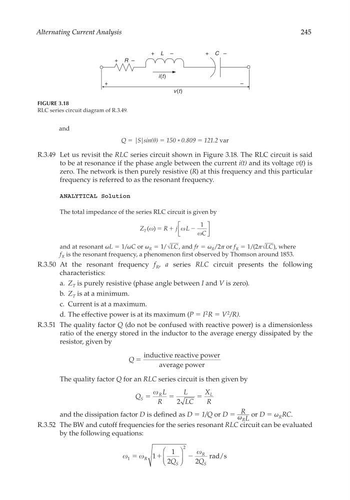
R.3.49 Let us revisit the RLC series circuit shown in Figure 3.18. The RLC circuit is said
to be at resonance if the phase angle between the current i(t) and its voltage v(t) is
zero. The network is then purely resistive (R) at this frequency and this particular
frequency is referred to as the resonant frequency.
ANALYTICAL Solution
The total impedance of the series RLC circuit is given by
Z
R j L
C
T ( )
ϭ ϩ
Ϫ
1
and at resonant ωL = 1/ωC or ω R = 1/ √
___
LC , and fr = ω R /2π or f R = 1/(2π √
___
LC ), where
f R is the resonant frequency, a phenomenon fi rst observed by Thomson around 1853.
R.3.50 At the resonant frequency f R , a series RLC circuit presents the following
characteristics:
a. Z T is purely resistive (phase angle between I and V is zero).
b. Z T is at a minimum.
c. Current is at a maximum.
d. The effective power is at its maximum (P = I
2 R = V
2 /R).
R.3.51 The quality factor Q (do not be confused with reactive power) is a dimensionless
ratio of the energy stored in the inductor to the average energy dissipated by the
resistor, given by
Q ϭ
inductive reactive power
average power
The quality factor Q for an RLC series circuit is then given by
Q
L
R
L
LC
X
R
S
R
L
ϭ
ϭ
ϭ
2
and the dissipation factor D is defi ned as D = 1/Q or D = R
____
ω RL
or D = ω R RC.
R.3.52 The BW and cutoff frequencies for the series resonant RLC circuit can be evaluated
by the following equations:
1
2
1
1
2
2
ϭ
ϩ
Ϫ
R
S
R
S
Q
Q
rad/s
i(t)
v(t)
+ L –
+ R –
+ C –
–
+
FIGURE 3.18
RLC series circuit diagram of R.3.49.
CRC_47760_CH003.indd 245
CRC_47760_CH003.indd 245
7/23/2008 1:27:36 PM
7/23/2008 1:27:36 PM
245
and
Q = |S|sin() = 150 * 0.809 = 121.2 var
R.3.49 Let us revisit the RLC series circuit shown in Figure 3.18. The RLC circuit is said
to be at resonance if the phase angle between the current i(t) and its voltage v(t) is
zero. The network is then purely resistive (R) at this frequency and this particular
frequency is referred to as the resonant frequency.
ANALYTICAL Solution
The total impedance of the series RLC circuit is given by
Z
R j L
C
T ( )
ϭ ϩ
Ϫ
1
and at resonant ωL = 1/ωC or ω R = 1/ √
___
LC , and fr = ω R /2π or f R = 1/(2π √
___
LC ), where
f R is the resonant frequency, a phenomenon fi rst observed by Thomson around 1853.
R.3.50 At the resonant frequency f R , a series RLC circuit presents the following
characteristics:
a. Z T is purely resistive (phase angle between I and V is zero).
b. Z T is at a minimum.
c. Current is at a maximum.
d. The effective power is at its maximum (P = I
2 R = V
2 /R).
R.3.51 The quality factor Q (do not be confused with reactive power) is a dimensionless
ratio of the energy stored in the inductor to the average energy dissipated by the
resistor, given by
Q ϭ
inductive reactive power
average power
The quality factor Q for an RLC series circuit is then given by
Q
L
R
L
LC
X
R
S
R
L
ϭ
ϭ
ϭ
2
and the dissipation factor D is defi ned as D = 1/Q or D = R
____
ω RL
or D = ω R RC.
R.3.52 The BW and cutoff frequencies for the series resonant RLC circuit can be evaluated
by the following equations:
1
2
1
1
2
2
ϭ
ϩ
Ϫ
R
S
R
S
Q
Q
rad/s
i(t)
v(t)
+ L –
+ R –
+ C –
–
+
FIGURE 3.18
RLC series circuit diagram of R.3.49.
CRC_47760_CH003.indd 245
CRC_47760_CH003.indd 245
7/23/2008 1:27:36 PM
7/23/2008 1:27:36 PM