

Alternating Current Analysis
237
where G = 1/R then
i(t) = V m|Y| cos(t + )
where θ = tan
−1
(−R/ωL).
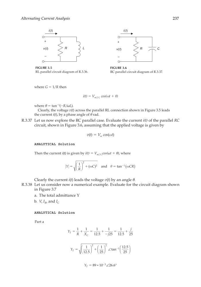
Clearly, the voltage v(t) across the parallel RL connection shown in Figure 3.5 leads
the current i(t), by a phase angle of θ rad.
R.3.37 Let us now explore the RC parallel case. Evaluate the current i(t) of the parallel RC
circuit, shown in Figure 3.6, assuming that the applied voltage is given by
v (t) = V m cos(t)
ANALYTICAL Solution
Then the current i(t) is given by i(t) = V m|Y| cos(ωt + θ), where
Y
R
C
C R
ϭ
ϩ
ϭ
Ϫ
1
2
2
1
(
)
( )
tan
and
Clearly the current i(t) leads the voltage v(t) by an angle θ.
R.3.38 Let us consider now a numerical example. Evaluate for the circuit diagram shown
in Figure 3.7
a. The total admittance Y
b. V, I R , and I C
ANALYTICAL Solution
Part a
Y
R X
j
j
T
C
ϭ ϩ
ϭ
ϩ Ϫ
ϭ
ϩ
1
1
1
12 5
1
25
1
12 5 25
.
.
Y T ϭ
ϩ
Ϫ
1
12 5
1
25
12 5
25
2
2
1
.
tan
.
∠
Y T ϭ
Ϫ
89 10
26 6
3
*
∠ . °
FIGURE 3.5
RL parallel circuit diagram of R.3.36.
i(t)
L
R
+
v(t)
–
FIGURE 3.6
RC parallel circuit diagram of R.3.37.
i (t )
C
R
+
v(t)
–
CRC_47760_CH003.indd 237
CRC_47760_CH003.indd 237
7/23/2008 1:27:32 PM
7/23/2008 1:27:32 PM
237
where G = 1/R then
i(t) = V m|Y| cos(t + )
where θ = tan
−1
(−R/ωL).
Clearly, the voltage v(t) across the parallel RL connection shown in Figure 3.5 leads
the current i(t), by a phase angle of θ rad.
R.3.37 Let us now explore the RC parallel case. Evaluate the current i(t) of the parallel RC
circuit, shown in Figure 3.6, assuming that the applied voltage is given by
v (t) = V m cos(t)
ANALYTICAL Solution
Then the current i(t) is given by i(t) = V m|Y| cos(ωt + θ), where
Y
R
C
C R
ϭ
ϩ
ϭ
Ϫ
1
2
2
1
(
)
( )
tan
and
Clearly the current i(t) leads the voltage v(t) by an angle θ.
R.3.38 Let us consider now a numerical example. Evaluate for the circuit diagram shown
in Figure 3.7
a. The total admittance Y
b. V, I R , and I C
ANALYTICAL Solution
Part a
Y
R X
j
j
T
C
ϭ ϩ
ϭ
ϩ Ϫ
ϭ
ϩ
1
1
1
12 5
1
25
1
12 5 25
.
.
Y T ϭ
ϩ
Ϫ
1
12 5
1
25
12 5
25
2
2
1
.
tan
.
∠
Y T ϭ
Ϫ
89 10
26 6
3
*
∠ . °
FIGURE 3.5
RL parallel circuit diagram of R.3.36.
i(t)
L
R
+
v(t)
–
FIGURE 3.6
RC parallel circuit diagram of R.3.37.
i (t )
C
R
+
v(t)
–
CRC_47760_CH003.indd 237
CRC_47760_CH003.indd 237
7/23/2008 1:27:32 PM
7/23/2008 1:27:32 PM