

236
Practical MATLAB
® Applications for Engineers
ANALYTICAL Solution
X L = jL = j * 1000 * 0.02 = j20
X
j
C
j
j
C ϭ
Ϫ ϭ
Ϫ
ϭ Ϫ
Ϫ
1000 20 10
50
6
*
*
X = X L + X C = j20 − j50 = −j30
Then, Z = R + X = (20 − j30) and
G
Z
j
j
j
ϭ ϭ
Ϫ
ϭ
ϩ
ϩ
ϩ
ϭ
ϩ
Ϫ
1
1
20
30
20
20
30
30
20
30
2
130
3
130
2
2
2
2
1
(or si ie)
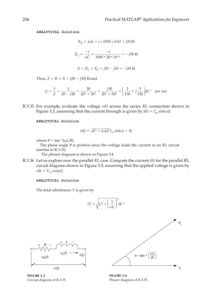
R.3.35 For example, evaluate the voltage v(t) across the series RL connection shown in
Figure 3.3, assuming that the current through is given by i(t) = I m sin(t).
ANALYTICAL Solution
v(t) = √
__________
R
2
+ (L)
2 I m sin(t + )
where θ = tan
−1
(ωL/R).
The phase angle θ is positive since the voltage leads the current in an RL circuit
(similar to R.3.31).
The phasor diagram is shown in Figure 3.4.
R.3.36 Let us explore now the parallel RL case. Compute the current i(t) for the parallel RL
circuit diagram shown in Figure 3.5, assuming that the applied voltage is given by
v(t) = V m cos(ωt)
ANALYTICAL Solution
The total admittance Y is given by
Y
G
L
ϭ
ϩ
Ϫ
2
2
1
1
FIGURE 3.3
Circuit diagram of R.3.35.
+ R –
+ L –
v R (t)
i (t)
v L (t)
v (t)
–
+
FIGURE 3.4
Phasor diagram of R.3.35.
=
R
L
ω
θ tan −1
V L
I L
CRC_47760_CH003.indd 236
CRC_47760_CH003.indd 236
7/23/2008 1:27:32 PM
7/23/2008 1:27:32 PM
Practical MATLAB
® Applications for Engineers
ANALYTICAL Solution
X L = jL = j * 1000 * 0.02 = j20
X
j
C
j
j
C ϭ
Ϫ ϭ
Ϫ
ϭ Ϫ
Ϫ
1000 20 10
50
6
*
*
X = X L + X C = j20 − j50 = −j30
Then, Z = R + X = (20 − j30) and
G
Z
j
j
j
ϭ ϭ
Ϫ
ϭ
ϩ
ϩ
ϩ
ϭ
ϩ
Ϫ
1
1
20
30
20
20
30
30
20
30
2
130
3
130
2
2
2
2
1
(or si ie)
R.3.35 For example, evaluate the voltage v(t) across the series RL connection shown in
Figure 3.3, assuming that the current through is given by i(t) = I m sin(t).
ANALYTICAL Solution
v(t) = √
__________
R
2
+ (L)
2 I m sin(t + )
where θ = tan
−1
(ωL/R).
The phase angle θ is positive since the voltage leads the current in an RL circuit
(similar to R.3.31).
The phasor diagram is shown in Figure 3.4.
R.3.36 Let us explore now the parallel RL case. Compute the current i(t) for the parallel RL
circuit diagram shown in Figure 3.5, assuming that the applied voltage is given by
v(t) = V m cos(ωt)
ANALYTICAL Solution
The total admittance Y is given by
Y
G
L
ϭ
ϩ
Ϫ
2
2
1
1
FIGURE 3.3
Circuit diagram of R.3.35.
+ R –
+ L –
v R (t)
i (t)
v L (t)
v (t)
–
+
FIGURE 3.4
Phasor diagram of R.3.35.
=
R
L
ω
θ tan −1
V L
I L
CRC_47760_CH003.indd 236
CRC_47760_CH003.indd 236
7/23/2008 1:27:32 PM
7/23/2008 1:27:32 PM