

216
Practical MATLAB
® Applications for Engineers
P.2.25 For the circuit shown in Figure 2.121, evaluate
a. I 1 , I 2 , I 3 , I 4 , and I 5
b. V X , V Y , and V XY
c. Power of all the resistors in watts, horsepower, and foot-pound force per second
(see P.2.1)
d. The energy stored in C 1 , C 2 , and L
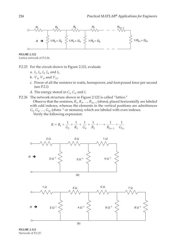
P.2.26 The network structure shown in Figure 2.122 is called “lattice.”
Observe that the resistors, R 1 , R 3 , …, R 2n−1 (ohms), placed horizontally are labeled
with odd indexes, whereas the elements in the vertical positions are admittances
G 1 , G 4 , …, G 2n (ohms
−1 or siemans), which are labeled with even indexes.
Verify the following expression:
R R
G
R
G
R
R
G
n
n
ϭ ϩ
ϩ
ϩ
ϩ
ϩ ϩ
ϩ
1
2
3
4
5
2 1
2
1
1
1
1
1
1
Ϫ
FIGURE 2.123
Network of P.2.27.
2 Ω
3 Ω
1 Ω
1 Ω
3 Ω
5 Ω
7 Ω
2 Ω −1
3 Ω
−1
4 Ω
−1
2 Ω
−1
4 Ω
−1
6 Ω
−1
8 Ω
−1
(a)
(b)
R
R
FIGURE 2.122
Lattice network of P.2.26.
1/R 2 = G 2
1/R 4 = G 4
1/R 6 = G 6
1/R 2n = G 2n
R 7
R 5
R 3
R 1
R
R 2n−1
CRC_47760_CH002.indd 216
CRC_47760_CH002.indd 216
7/23/2008 1:39:04 PM
7/23/2008 1:39:04 PM
Practical MATLAB
® Applications for Engineers
P.2.25 For the circuit shown in Figure 2.121, evaluate
a. I 1 , I 2 , I 3 , I 4 , and I 5
b. V X , V Y , and V XY
c. Power of all the resistors in watts, horsepower, and foot-pound force per second
(see P.2.1)
d. The energy stored in C 1 , C 2 , and L
P.2.26 The network structure shown in Figure 2.122 is called “lattice.”
Observe that the resistors, R 1 , R 3 , …, R 2n−1 (ohms), placed horizontally are labeled
with odd indexes, whereas the elements in the vertical positions are admittances
G 1 , G 4 , …, G 2n (ohms
−1 or siemans), which are labeled with even indexes.
Verify the following expression:
R R
G
R
G
R
R
G
n
n
ϭ ϩ
ϩ
ϩ
ϩ
ϩ ϩ
ϩ
1
2
3
4
5
2 1
2
1
1
1
1
1
1
Ϫ
FIGURE 2.123
Network of P.2.27.
2 Ω
3 Ω
1 Ω
1 Ω
3 Ω
5 Ω
7 Ω
2 Ω −1
3 Ω
−1
4 Ω
−1
2 Ω
−1
4 Ω
−1
6 Ω
−1
8 Ω
−1
(a)
(b)
R
R
FIGURE 2.122
Lattice network of P.2.26.
1/R 2 = G 2
1/R 4 = G 4
1/R 6 = G 6
1/R 2n = G 2n
R 7
R 5
R 3
R 1
R
R 2n−1
CRC_47760_CH002.indd 216
CRC_47760_CH002.indd 216
7/23/2008 1:39:04 PM
7/23/2008 1:39:04 PM