

Direct Current and Transient Analysis
215
P.2.22 The RL circuit in Figure 2.118 presents an initial current i(0) = 0 A at the instant the
switch closes at t = 0, where it remains indefi nitely. Write a program that returns
the following plots over the range 0 ≤ t ≤ 10 s:
a. [Current i(t)] versus t
b. Voltage v R (t) versus t
c. Voltage v L (t) versus t
d. [Energy w L in Joules stored in L] versus t
e. [Power in watts dissipated by R] versus t
P.2.23 Determine V L2 and V C2 shown in the circuits of Figure 2.119 in a tablelike format;
given V = 100 V, L 2 = 10 H, and C 2 = 10 F for the following cases:
a. L 1 varies from L 2 /2 to 2L 2 in linear steps of L 2 /10.
b. C 1 varies from C 2 /2 to 2C 2 in linear steps of C 2 /10.
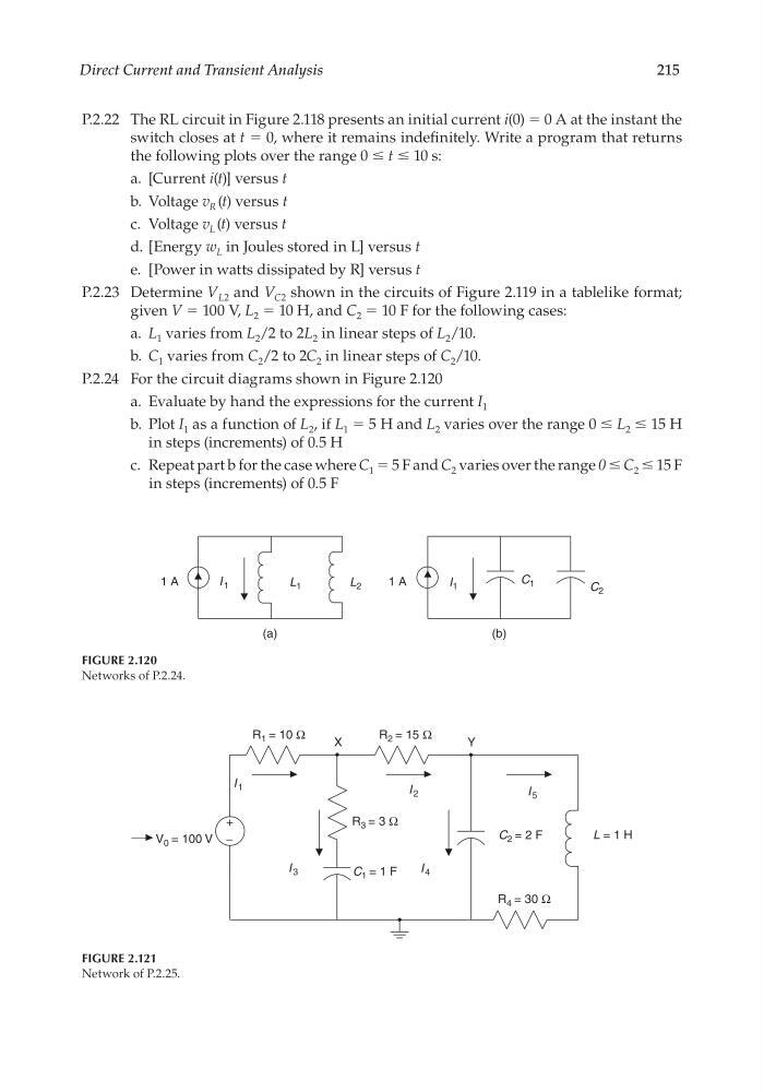
P.2.24 For the circuit diagrams shown in Figure 2.120
a. Evaluate by hand the expressions for the current I 1
b. Plot I 1 as a function of L 2 , if L 1 = 5 H and L 2 varies over the range 0 ≤ L 2 ≤ 15 H
in steps (increments) of 0.5 H
c. Repeat part b for the case where C 1 = 5 F and C 2 varies over the range 0 ≤ C 2 ≤ 15 F
in steps (increments) of 0.5 F
FIGURE 2.120
Networks of P.2.24.
L 1
1 A
1 A
(a)
L 2
I 1
C 2
C 1
I 1
(b)
FIGURE 2.121
Network of P.2.25.
V 0 = 100 V
R 3 = 3 Ω
R 1 = 10 Ω
R 2 = 15 Ω
R 4 = 30 Ω
I 5
I 2
I 1
I 3
I 4
C 1 = 1 F
C 2 = 2 F
L = 1 H
+
−
X
Y
CRC_47760_CH002.indd 215
CRC_47760_CH002.indd 215
7/23/2008 1:39:04 PM
7/23/2008 1:39:04 PM
215
P.2.22 The RL circuit in Figure 2.118 presents an initial current i(0) = 0 A at the instant the
switch closes at t = 0, where it remains indefi nitely. Write a program that returns
the following plots over the range 0 ≤ t ≤ 10 s:
a. [Current i(t)] versus t
b. Voltage v R (t) versus t
c. Voltage v L (t) versus t
d. [Energy w L in Joules stored in L] versus t
e. [Power in watts dissipated by R] versus t
P.2.23 Determine V L2 and V C2 shown in the circuits of Figure 2.119 in a tablelike format;
given V = 100 V, L 2 = 10 H, and C 2 = 10 F for the following cases:
a. L 1 varies from L 2 /2 to 2L 2 in linear steps of L 2 /10.
b. C 1 varies from C 2 /2 to 2C 2 in linear steps of C 2 /10.
P.2.24 For the circuit diagrams shown in Figure 2.120
a. Evaluate by hand the expressions for the current I 1
b. Plot I 1 as a function of L 2 , if L 1 = 5 H and L 2 varies over the range 0 ≤ L 2 ≤ 15 H
in steps (increments) of 0.5 H
c. Repeat part b for the case where C 1 = 5 F and C 2 varies over the range 0 ≤ C 2 ≤ 15 F
in steps (increments) of 0.5 F
FIGURE 2.120
Networks of P.2.24.
L 1
1 A
1 A
(a)
L 2
I 1
C 2
C 1
I 1
(b)
FIGURE 2.121
Network of P.2.25.
V 0 = 100 V
R 3 = 3 Ω
R 1 = 10 Ω
R 2 = 15 Ω
R 4 = 30 Ω
I 5
I 2
I 1
I 3
I 4
C 1 = 1 F
C 2 = 2 F
L = 1 H
+
−
X
Y
CRC_47760_CH002.indd 215
CRC_47760_CH002.indd 215
7/23/2008 1:39:04 PM
7/23/2008 1:39:04 PM