

162
Practical MATLAB
® Applications for Engineers
2. The resulting system nodal matrix equation is given by
3
1
1 4
2
3
Ϫ
Ϫ
Y
V
V
I
X
Y
* V
ϭ
where Y is the admittance matrix of the network, and the current vector I is given by
I ϭ
2
3
MATLAB Solution
>> Y = [3 -1;-1 4];
>> I = [2;3];
>> V= inv(Y)*I;
>> VX = V(1);
>> VY =V(2);
>> Result = [VX VY];
>> disp (‘**********************************’)
>> disp (‘The voltage drops Vx and Vy (in volts) are given by:’);
>> disp (Result)
>> disp (‘**********************************’)
************************************************************
The nodal voltages Vx and Vy (in volts) are given by:
1.0000
1.0000
************************************************************
Example 2.19
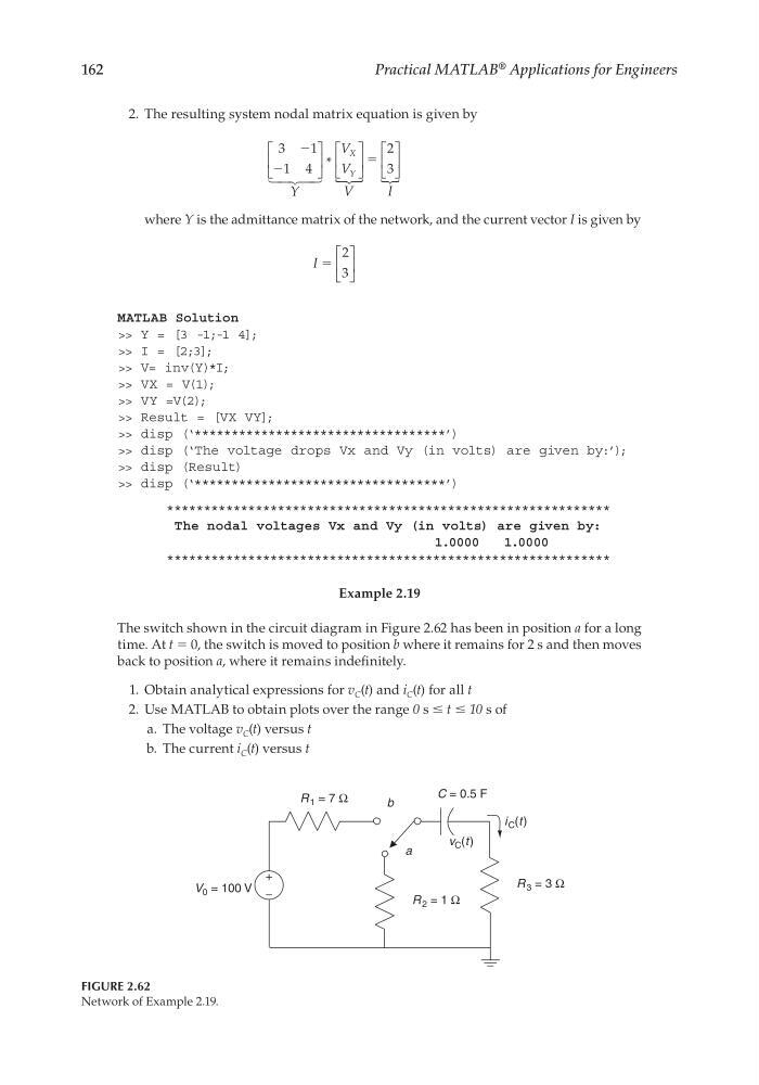
The switch shown in the circuit diagram in Figure 2.62 has been in position a for a long
time. At t = 0, the switch is moved to position b where it remains for 2 s and then moves
back to position a, where it remains indefi nitely.
1. Obtain analytical expressions for v C (t) and i C (t) for all t
2. Use MATLAB to obtain plots over the range 0 s ≤ t ≤ 10 s of
a. The voltage v C (t) versus t
b. The current i C (t) versus t
FIGURE 2.62
Network of Example 2.19.
b
a
R 3 = 3 Ω
R 2 = 1 Ω
R 1 = 7 Ω
V 0 = 100 V
C = 0.5 F
i C (t )
v C (t )
+
−
CRC_47760_CH002.indd 162
CRC_47760_CH002.indd 162
7/23/2008 1:38:51 PM
7/23/2008 1:38:51 PM
Practical MATLAB
® Applications for Engineers
2. The resulting system nodal matrix equation is given by
3
1
1 4
2
3
Ϫ
Ϫ
Y
V
V
I
X
Y
* V
ϭ
where Y is the admittance matrix of the network, and the current vector I is given by
I ϭ
2
3
MATLAB Solution
>> Y = [3 -1;-1 4];
>> I = [2;3];
>> V= inv(Y)*I;
>> VX = V(1);
>> VY =V(2);
>> Result = [VX VY];
>> disp (‘**********************************’)
>> disp (‘The voltage drops Vx and Vy (in volts) are given by:’);
>> disp (Result)
>> disp (‘**********************************’)
************************************************************
The nodal voltages Vx and Vy (in volts) are given by:
1.0000
1.0000
************************************************************
Example 2.19
The switch shown in the circuit diagram in Figure 2.62 has been in position a for a long
time. At t = 0, the switch is moved to position b where it remains for 2 s and then moves
back to position a, where it remains indefi nitely.
1. Obtain analytical expressions for v C (t) and i C (t) for all t
2. Use MATLAB to obtain plots over the range 0 s ≤ t ≤ 10 s of
a. The voltage v C (t) versus t
b. The current i C (t) versus t
FIGURE 2.62
Network of Example 2.19.
b
a
R 3 = 3 Ω
R 2 = 1 Ω
R 1 = 7 Ω
V 0 = 100 V
C = 0.5 F
i C (t )
v C (t )
+
−
CRC_47760_CH002.indd 162
CRC_47760_CH002.indd 162
7/23/2008 1:38:51 PM
7/23/2008 1:38:51 PM