

7.3 Conversion of PET into Carbonaceous Nanomaterials
119
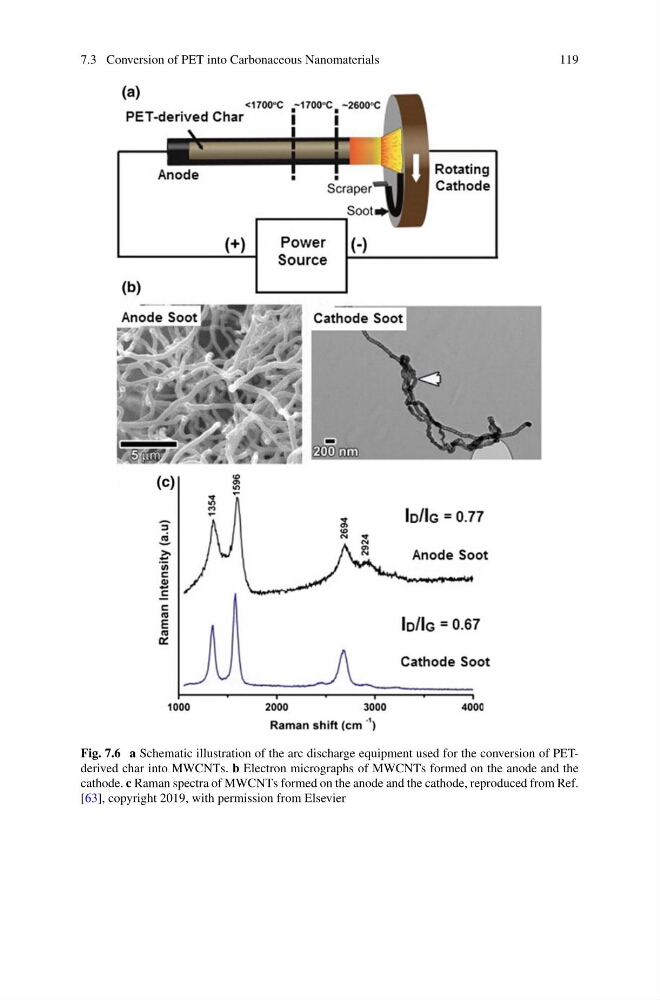
Fig. 7.6 a Schematic illustration of the arc discharge equipment used for the conversion of PETderived char into MWCNTs. b Electron micrographs of MWCNTs formed on the anode and the
cathode. c Raman spectra of MWCNTs formed on the anode and the cathode, reproduced from Ref.
[63], copyright 2019, with permission from Elsevier
119
Fig. 7.6 a Schematic illustration of the arc discharge equipment used for the conversion of PETderived char into MWCNTs. b Electron micrographs of MWCNTs formed on the anode and the
cathode. c Raman spectra of MWCNTs formed on the anode and the cathode, reproduced from Ref.
[63], copyright 2019, with permission from Elsevier