

M × N × (⎡
⎡
⎢ C/M N ⎤ ⎥ ) × M + N + (⎡ ⎢ C/ MN ⎤ ⎥
⎣
) ⎤ ⎦
− (⎡ ⎢ C/ M N ⎤ ⎥ ) × (M + N ) − MN
D =
3 ⎡ M × N N × ⎡C/ MN ⎤
⎣
( ⎢
⎥ ) − 1 ⎤ ⎦
⎧ M × N × ( ⎡ ⎢ C/ MN ⎥ ⎤ − 1 ) + N × ⎡ ⎢ C/ M N ⎤
⎫
⎥ × (M − 1
⎪
) ⎪
E = 2 × ⎨
⎬
⎪ ⎪
+ M × ⎡ ⎢ C/ M N ⎤ ⎥ × (N − 1)
⎪
⎩
⎭
339
Three-Dimensional Integration of Network-on-Chip
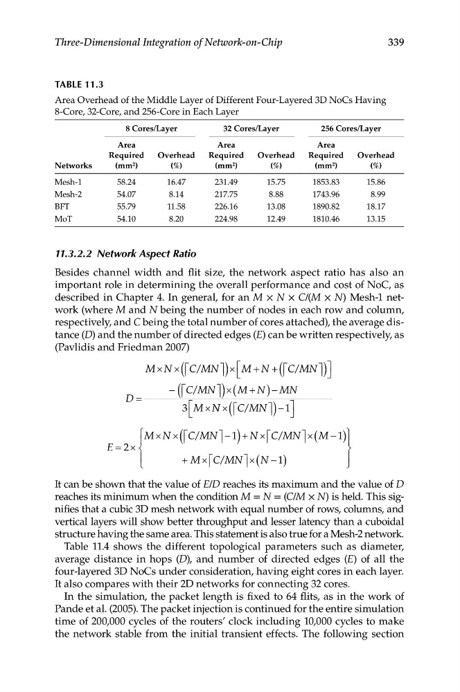
TABLe 11.3
Area Overhead of the Middle Layer of Different Four-Layered 3D NoCs Having
8-Core, 32-Core, and 256-Core in Each Layer
8 Cores/Layer
32 Cores/Layer
256 Cores/Layer
Networks
Area
Required
(mm 2 )
Overhead
(%)
Area
Required
(mm 2 )
Overhead
(%)
Area
Required
(mm 2 )
Overhead
(%)
Mesh-1
58.24
16.47
231.49
15.75
1853.83
15.86
Mesh-2
54.07
8.14
217.75
8.88
1743.96
8.99
BFT
55.79
11.58
226.16
13.08
1890.82
18.17
MoT
54.10
8.20
224.98
12.49
1810.46
13.15
11.3.2.2 Network Aspect Ratio
Besides channel width and flit size, the network aspect ratio has also an
important role in determining the overall performance and cost of NoC, as
described in Chapter 4. In general, for an M × N × C/(M × N) Mesh-1 network (where M and N being the number of nodes in each row and column,
respectively, and C being the total number of cores attached), the average distance (D) and the number of directed edges (E) can be written respectively, as
(Pavlidis and Friedman 2007)
It can be shown that the value of E/D reaches its maximum and the value of D
reaches its minimum when the condition M = N = (C/M × N) is held. This signifies that a cubic 3D mesh network with equal number of rows, columns, and
vertical layers will show better throughput and lesser latency than a cuboidal
structure having the same area. This statement is also true for a Mesh-2 network.
Table 11.4 shows the different topological parameters such as diameter,
average distance in hops (D), and number of directed edges (E) of all the
four-layered 3D NoCs under consideration, having eight cores in each layer.
It also compares with their 2D networks for connecting 32 cores.
In the simulation, the packet length is fixed to 64 flits, as in the work of
Pande et al. (2005). The packet injection is continued for the entire simulation
time of 200,000 cycles of the routers’ clock including 10,000 cycles to make
the network stable from the initial transient effects. The following section