

334
Network-on-Chip
≈20 μm
≈10 mm
≈ 5 m m
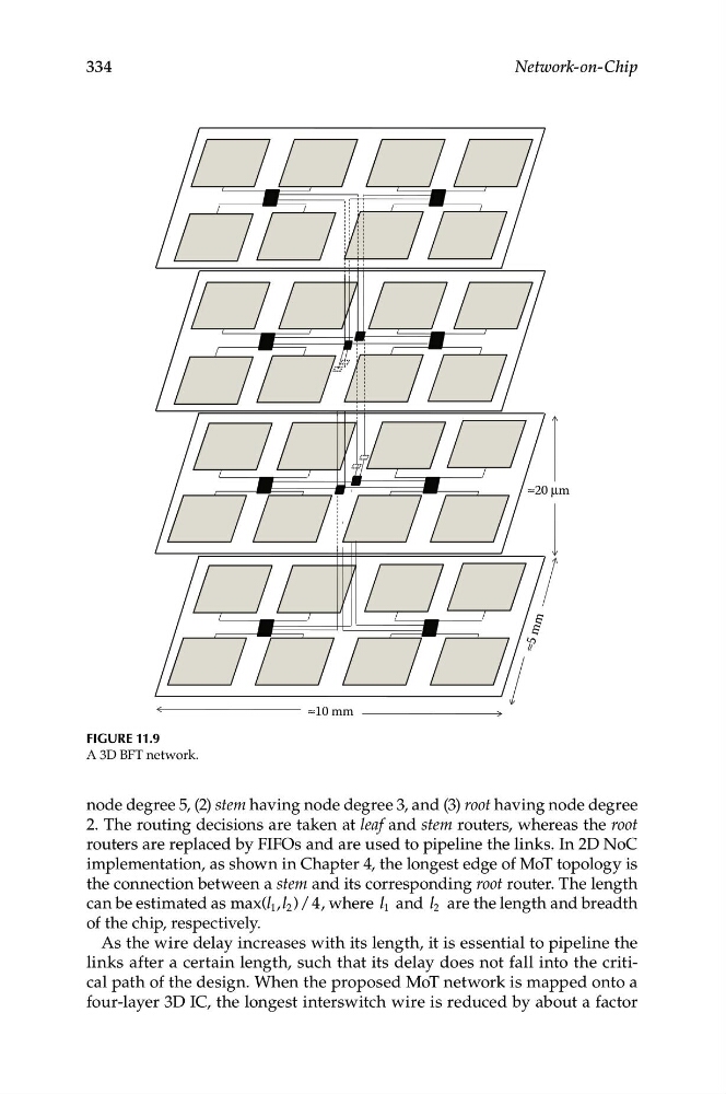
Figure 11.9
A 3D BFT network.
node degree 5, (2) stem having node degree 3, and (3) root having node degree
2. The routing decisions are taken at leaf and stem routers, whereas the root
routers are replaced by FIFOs and are used to pipeline the links. In 2D NoC
implementation, as shown in Chapter 4, the longest edge of MoT topology is
the connection between a stem and its corresponding root router. The length
can be estimated as max (l 1 ,l 2 )/ 4, where l 1 and l 2 are the length and breadth
of the chip, respectively.
As the wire delay increases with its length, it is essential to pipeline the
links after a certain length, such that its delay does not fall into the critical path of the design. When the proposed MoT network is mapped onto a
four-layer 3D IC, the longest interswitch wire is reduced by about a factor
Network-on-Chip
≈20 μm
≈10 mm
≈ 5 m m
Figure 11.9
A 3D BFT network.
node degree 5, (2) stem having node degree 3, and (3) root having node degree
2. The routing decisions are taken at leaf and stem routers, whereas the root
routers are replaced by FIFOs and are used to pipeline the links. In 2D NoC
implementation, as shown in Chapter 4, the longest edge of MoT topology is
the connection between a stem and its corresponding root router. The length
can be estimated as max (l 1 ,l 2 )/ 4, where l 1 and l 2 are the length and breadth
of the chip, respectively.
As the wire delay increases with its length, it is essential to pipeline the
links after a certain length, such that its delay does not fall into the critical path of the design. When the proposed MoT network is mapped onto a
four-layer 3D IC, the longest interswitch wire is reduced by about a factor