

324
Network-on-Chip
(a)
(c)
(b)
(d)
y
y
x
z
Coordinate axes
IP block
Switch
Interconnect
Bus
Bus node
2.5 mm
~μm
l NOC
l NOC l NOC
2
=
x
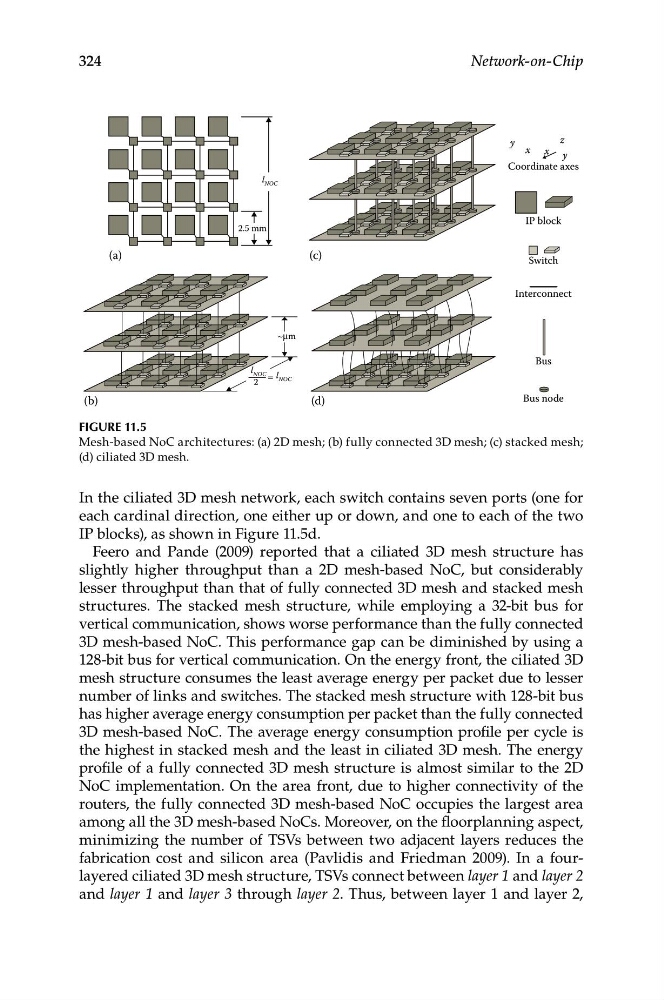
Figure 11.5
Mesh-based NoC architectures: (a) 2D mesh; (b) fully connected 3D mesh; (c) stacked mesh;
(d) ciliated 3D mesh.
In the ciliated 3D mesh network, each switch contains seven ports (one for
each cardinal direction, one either up or down, and one to each of the two
IP blocks), as shown in Figure 11.5d.
Feero and Pande (2009) reported that a ciliated 3D mesh structure has
slightly higher throughput than a 2D mesh-based NoC, but considerably
lesser throughput than that of fully connected 3D mesh and stacked mesh
structures. The stacked mesh structure, while employing a 32-bit bus for
vertical communication, shows worse performance than the fully connected
3D mesh-based NoC. This performance gap can be diminished by using a
128-bit bus for vertical communication. On the energy front, the ciliated 3D
mesh structure consumes the least average energy per packet due to lesser
number of links and switches. The stacked mesh structure with 128-bit bus
has higher average energy consumption per packet than the fully connected
3D mesh-based NoC. The average energy consumption profile per cycle is
the highest in stacked mesh and the least in ciliated 3D mesh. The energy
profile of a fully connected 3D mesh structure is almost similar to the 2D
NoC implementation. On the area front, due to higher connectivity of the
routers, the fully connected 3D mesh-based NoC occupies the largest area
among all the 3D mesh-based NoCs. Moreover, on the floorplanning aspect,
minimizing the number of TSVs between two adjacent layers reduces the
fabrication cost and silicon area (Pavlidis and Friedman 2009). In a fourlayered ciliated 3D mesh structure, TSVs connect between layer 1 and layer 2
and layer 1 and layer 3 through layer 2. Thus, between layer 1 and layer 2,