

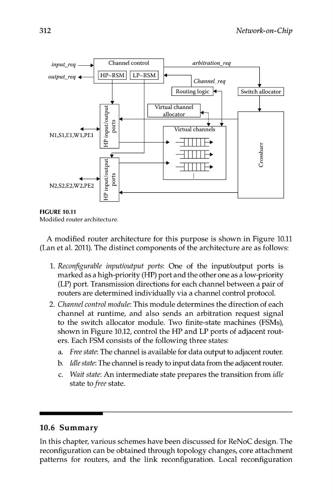
1. Reconfigurable input/output ports: One of the input/output ports is
marked as a high-priority (HP) port and the other one as a low- priority
(LP) port. Transmission directions for each channel between a pair of
routers are determined individually via a channel control protocol.
2. Channel control module: This module determines the direction of each
channel at runtime, and also sends an arbitration request signal
to the switch allocator module. Two finite-state machines (FSMs),
shown in Figure 10.12, control the HP and LP ports of adjacent routers. Each FSM consists of the following three states:
a. Free state: The channel is available for data output to adjacent router.
b. Idle state: The channel is ready to input data from the adjacent router.
c. Wait state: An intermediate state prepares the transition from idle
state to free state.
312
Network-on-Chip
input_req
arbitration_req
Channel_req
Switch allocator
Virtual channels
Virtual channel
allocator
Channel control
HP–RSM LP–RSM
N1,S1,E1,W1,PE1
N2,S2,E2,W2,PE2
Routing logic
Crossbarr
HP input/output
ports
HP input/output
ports
output_req
Figure 10.11
Modified router architecture.
A modified router architecture for this purpose is shown in Figure 10.11
(Lan et al. 2011). The distinct components of the architecture are as follows:
10.6 Summary
In this chapter, various schemes have been discussed for ReNoC design. The
reconfiguration can be obtained through topology changes, core attachment
patterns for routers, and the link reconfiguration. Local reconfiguration
marked as a high-priority (HP) port and the other one as a low- priority
(LP) port. Transmission directions for each channel between a pair of
routers are determined individually via a channel control protocol.
2. Channel control module: This module determines the direction of each
channel at runtime, and also sends an arbitration request signal
to the switch allocator module. Two finite-state machines (FSMs),
shown in Figure 10.12, control the HP and LP ports of adjacent routers. Each FSM consists of the following three states:
a. Free state: The channel is available for data output to adjacent router.
b. Idle state: The channel is ready to input data from the adjacent router.
c. Wait state: An intermediate state prepares the transition from idle
state to free state.
312
Network-on-Chip
input_req
arbitration_req
Channel_req
Switch allocator
Virtual channels
Virtual channel
allocator
Channel control
HP–RSM LP–RSM
N1,S1,E1,W1,PE1
N2,S2,E2,W2,PE2
Routing logic
Crossbarr
HP input/output
ports
HP input/output
ports
output_req
Figure 10.11
Modified router architecture.
A modified router architecture for this purpose is shown in Figure 10.11
(Lan et al. 2011). The distinct components of the architecture are as follows:
10.6 Summary
In this chapter, various schemes have been discussed for ReNoC design. The
reconfiguration can be obtained through topology changes, core attachment
patterns for routers, and the link reconfiguration. Local reconfiguration