

298
Network-on-Chip
Core graph 1
Core graph 1
Construct CCG
CCG
Mapping of CCG
Initial mesh
mapping of CCG
Application-specific
Reconfiguration
Configuration of
core graph 1
Configuration of
core graph 2
Configuration of
core graph n
Core graph n
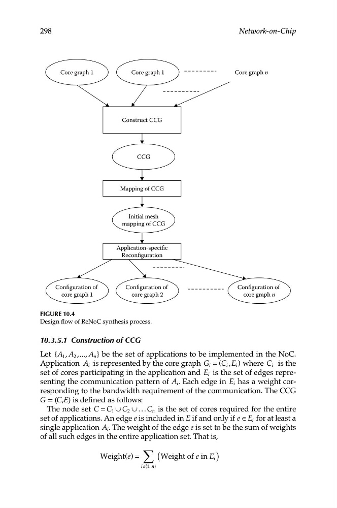
Figure 10.4
Design flow of ReNoC synthesis process.
10.3.5.1 Construction of CCG
Let {A 1 , A 2 ,..., A n } be the set of applications to be implemented in the NoC.
Application A i is represented by the core graph G i = (C i , E i ) where C i is the
set of cores participating in the application and E i is the set of edges representing the communication pattern of A i . Each edge in E i has a weight corresponding to the bandwidth requirement of the communication. The CCG
G = (C,E) is defined as follows:
The node set C = C 1 ∪ C 2 ∪ . . . C n is the set of cores required for the entire
set of applications. An edge e is included in E if and only if e ∈ E i for at least a
single application A i . The weight of the edge e is set to be the sum of weights
of all such edges in the entire application set. That is,
Weight ( )
e = ∑ (Weight of e in E i )
i∈{1.. n}