

294
Network-on-Chip
For an M × N network, the number of different types of multiplexers
needed are as follows:
4:1 multiplexers = (M − 1)(N − 1)
2:1 multiplexers = M + N − 2
10.3.3 Selection Logic
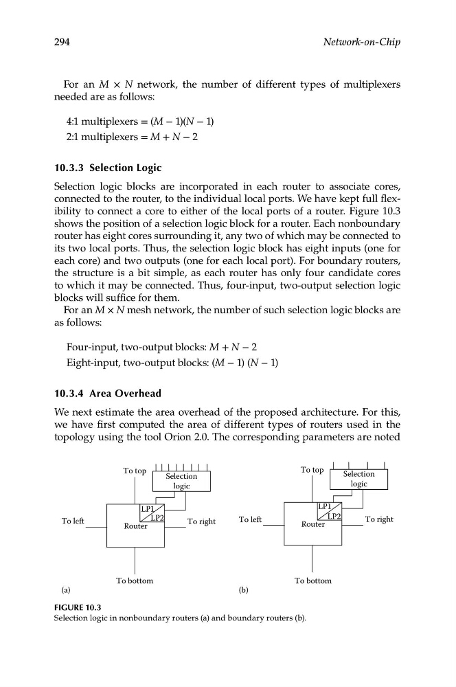
Selection logic blocks are incorporated in each router to associate cores,
connected to the router, to the individual local ports. We have kept full flexibility to connect a core to either of the local ports of a router. Figure 10.3
shows the position of a selection logic block for a router. Each nonboundary
router has eight cores surrounding it, any two of which may be connected to
its two local ports. Thus, the selection logic block has eight inputs (one for
each core) and two outputs (one for each local port). For boundary routers,
the structure is a bit simple, as each router has only four candidate cores
to which it may be connected. Thus, four-input, two-output selection logic
blocks will suffice for them.
For an M × N mesh network, the number of such selection logic blocks are
as follows:
Four-input, two-output blocks: M + N − 2
Eight-input, two-output blocks: (M − 1) (N − 1)
10.3.4 Area Overhead
We next estimate the area overhead of the proposed architecture. For this,
we have first computed the area of different types of routers used in the
topology using the tool Orion 2.0. The corresponding parameters are noted
To left
To left
To bottom
LP1
LP2
Router
Selection
logic
To top
To right
LP2
To right
To bottom
LP1
Router
Selection
logic
To top
(a)
(b)
Figure 10.3
Selection logic in nonboundary routers (a) and boundary routers (b).