

277
Application-Specific Network-on-Chip Synthesis
such a situation. The latency constraint of the original communication trace is
split into half across the edges attached to the dummy node pair for a cut edge.
The bandwidth constraint is duplicated. The MILP formulation is now run for
each of the clusters to generate the topologies for the subgraphs. The topologies
are then combined by establishing physical links between the dummy nodes,
thus generating the complete ASNoC.
9.6 ASNoC Synthesis with Flexible Router Placement
The ASNoC synthesis procedure discussed in Section 9.5 generates a floorplan in which routers are placed only at the corners of the tiles containing a
core and its associated routers. This may often lead to multihop connection
due to the link length constraints. In the work of Soumya and Chattopadhyay
(2013), the problem is addressed to generate a flexible placement of routers in
a given floorplan of the NoC containing only the cores.
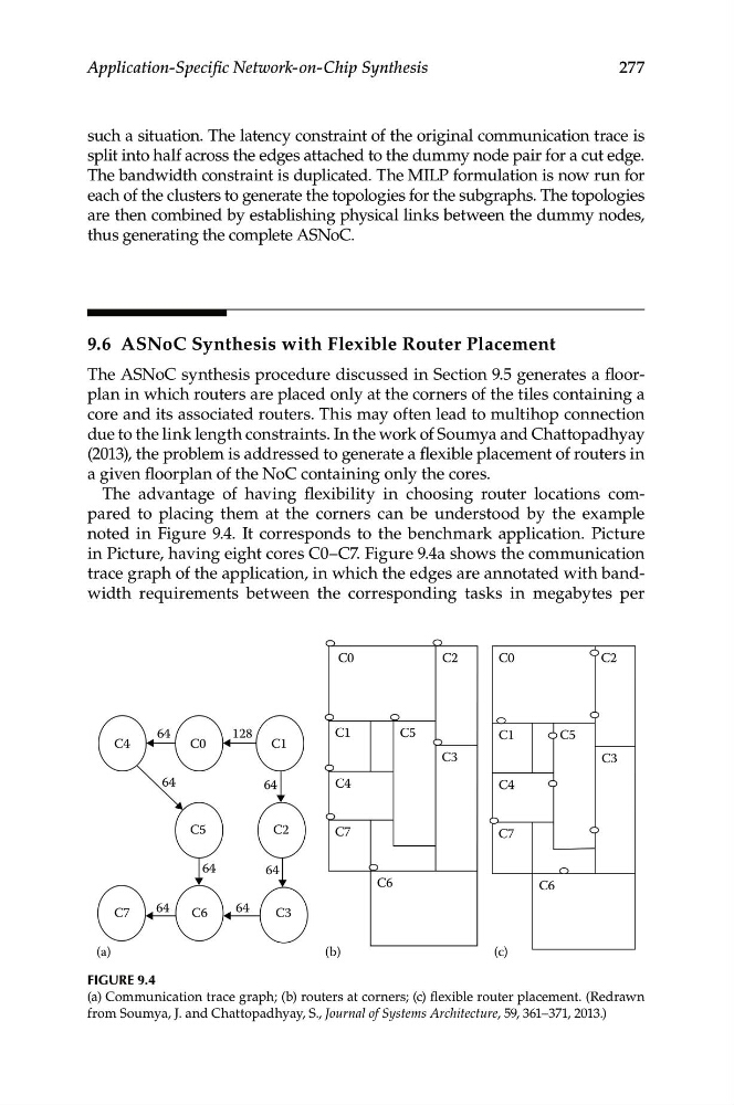
The advantage of having flexibility in choosing router locations compared to placing them at the corners can be understood by the example
noted in Figure 9.4. It corresponds to the benchmark application. Picture
in Picture, having eight cores C0–C7. Figure 9.4a shows the communication
trace graph of the application, in which the edges are annotated with bandwidth requirements between the corresponding tasks in megabytes per
C4
C7
(a)
(b)
(c)
C6
C3
C0
C5
C2
C1
C0
C1
C5
C4
C7
C6
C6
C3
C0
C1
C4
C5
C3
C7
C2
C2
64
64
64
64
64
64
64
128
Figure 9.4
(a) Communication trace graph; (b) routers at corners; (c) flexible router placement. (Redrawn
from Soumya, J. and Chattopadhyay, S., Journal of Systems Architecture, 59, 361–371, 2013.)