

Clustering
Dummy mode creation
R1
R3
Cluster solution generation
Full topology generation
A
B
A
B
B
A
R1
R3
R4
R2
R4
R2
B
A
276
Network-on-Chip
p m,n exists. Similarly, if a traffic leaves a port of a router, the port must
be mapped to a node or a port of a different router. That is,
NR j k l
, , +
RR k l m n
, ≥ I , , , and NR , , +
RR k l m n ≥ O , ,
, ,
j i k l
i k l
, , ,
j i k l
,
∑ ∑
∑ ∑
rm R pm n
,
∀ ∈
rm R ∀pm n
∀ ∈ ∀
,
• Latency: It can be stated as
∀e k = (v i , v j ) ∈ E,
O i j k l
, , , ≤ σ(e k )
∑ ∑
∀ ∈
rk R ∀pk l
,
The MILP formulation discussed above can produce optimum solution, however, takes exponential time for large communication trace graphs. A clustering heuristic was proposed by Roy (1978) to reduce the time requirement by
partitioning the trace graph into clusters of nodes. Cluster size is constrained
by the maximum number of nodes in a cluster, as specified by the designer. For
each edge e ∊ E, the clustering algorithm first assigns a distance metric, given by,
DF e
2
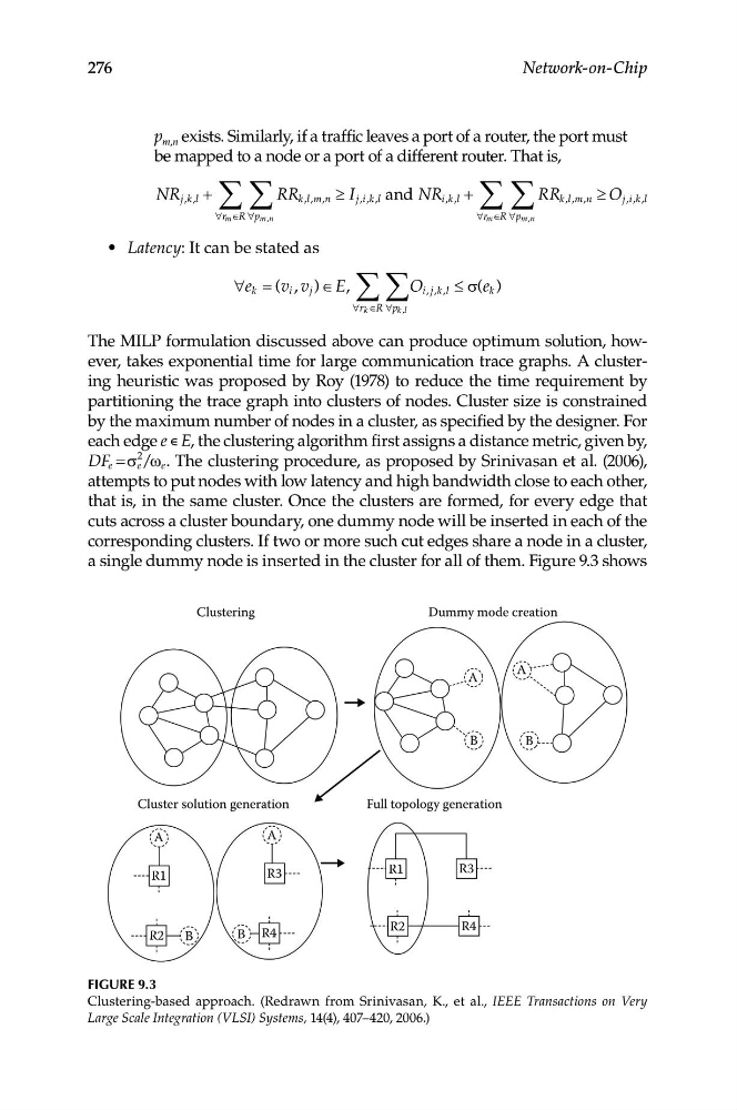
e / e . The clustering procedure, as proposed by Srinivasan et al. (2006),
= σ ω
attempts to put nodes with low latency and high bandwidth close to each other,
that is, in the same cluster. Once the clusters are formed, for every edge that
cuts across a cluster boundary, one dummy node will be inserted in each of the
corresponding clusters. If two or more such cut edges share a node in a cluster,
a single dummy node is inserted in the cluster for all of them. Figure 9.3 shows
Figure 9.3
Clustering-based approach. (Redrawn from Srinivasan, K., et al., IEEE Transactions on Very
Large Scale Integration (VLSI) Systems, 14(4), 407–420, 2006.)