

20
S. P. Donegan and M. A. Groeber
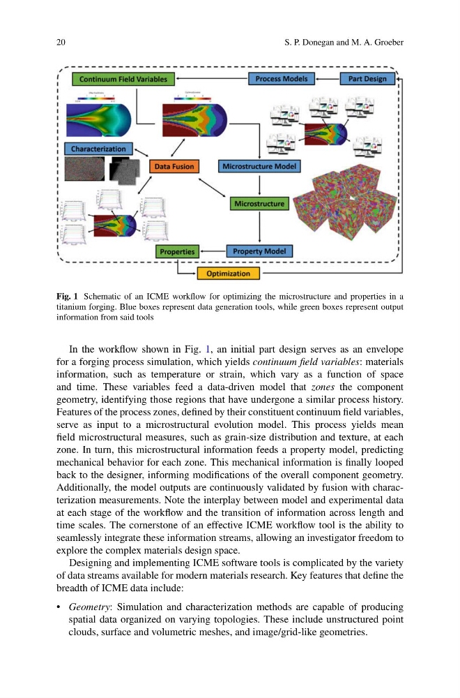
Fig. 1 Schematic of an ICME workflow for optimizing the microstructure and properties in a
titanium forging. Blue boxes represent data generation tools, while green boxes represent output
information from said tools
In the workflow shown in Fig. 1, an initial part design serves as an envelope
for a forging process simulation, which yields continuum field variables: materials
information, such as temperature or strain, which vary as a function of space
and time. These variables feed a data-driven model that zones the component
geometry, identifying those regions that have undergone a similar process history.
Features of the process zones, defined by their constituent continuum field variables,
serve as input to a microstructural evolution model. This process yields mean
field microstructural measures, such as grain-size distribution and texture, at each
zone. In turn, this microstructural information feeds a property model, predicting
mechanical behavior for each zone. This mechanical information is finally looped
back to the designer, informing modifications of the overall component geometry.
Additionally, the model outputs are continuously validated by fusion with characterization measurements. Note the interplay between model and experimental data
at each stage of the workflow and the transition of information across length and
time scales. The cornerstone of an effective ICME workflow tool is the ability to
seamlessly integrate these information streams, allowing an investigator freedom to
explore the complex materials design space.
Designing and implementing ICME software tools is complicated by the variety
of data streams available for modern materials research. Key features that define the
breadth of ICME data include:
• Geometry: Simulation and characterization methods are capable of producing
spatial data organized on varying topologies. These include unstructured point
clouds, surface and volumetric meshes, and image/grid-like geometries.
S. P. Donegan and M. A. Groeber
Fig. 1 Schematic of an ICME workflow for optimizing the microstructure and properties in a
titanium forging. Blue boxes represent data generation tools, while green boxes represent output
information from said tools
In the workflow shown in Fig. 1, an initial part design serves as an envelope
for a forging process simulation, which yields continuum field variables: materials
information, such as temperature or strain, which vary as a function of space
and time. These variables feed a data-driven model that zones the component
geometry, identifying those regions that have undergone a similar process history.
Features of the process zones, defined by their constituent continuum field variables,
serve as input to a microstructural evolution model. This process yields mean
field microstructural measures, such as grain-size distribution and texture, at each
zone. In turn, this microstructural information feeds a property model, predicting
mechanical behavior for each zone. This mechanical information is finally looped
back to the designer, informing modifications of the overall component geometry.
Additionally, the model outputs are continuously validated by fusion with characterization measurements. Note the interplay between model and experimental data
at each stage of the workflow and the transition of information across length and
time scales. The cornerstone of an effective ICME workflow tool is the ability to
seamlessly integrate these information streams, allowing an investigator freedom to
explore the complex materials design space.
Designing and implementing ICME software tools is complicated by the variety
of data streams available for modern materials research. Key features that define the
breadth of ICME data include:
• Geometry: Simulation and characterization methods are capable of producing
spatial data organized on varying topologies. These include unstructured point
clouds, surface and volumetric meshes, and image/grid-like geometries.