

356
A. Agrawal et al.
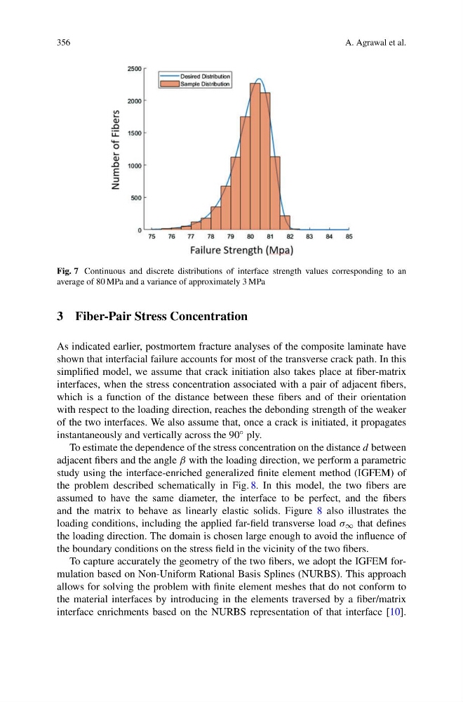
Fig. 7 Continuous and discrete distributions of interface strength values corresponding to an
average of 80 MPa and a variance of approximately 3 MPa
3 Fiber-Pair Stress Concentration
As indicated earlier, postmortem fracture analyses of the composite laminate have
shown that interfacial failure accounts for most of the transverse crack path. In this
simplified model, we assume that crack initiation also takes place at fiber-matrix
interfaces, when the stress concentration associated with a pair of adjacent fibers,
which is a function of the distance between these fibers and of their orientation
with respect to the loading direction, reaches the debonding strength of the weaker
of the two interfaces. We also assume that, once a crack is initiated, it propagates
instantaneously and vertically across the 90 ◦ ply.
To estimate the dependence of the stress concentration on the distance d between
adjacent fibers and the angle β with the loading direction, we perform a parametric
study using the interface-enriched generalized finite element method (IGFEM) of
the problem described schematically in Fig. 8. In this model, the two fibers are
assumed to have the same diameter, the interface to be perfect, and the fibers
and the matrix to behave as linearly elastic solids. Figure 8 also illustrates the
loading conditions, including the applied far-field transverse load σ ∞ that defines
the loading direction. The domain is chosen large enough to avoid the influence of
the boundary conditions on the stress field in the vicinity of the two fibers.
To capture accurately the geometry of the two fibers, we adopt the IGFEM formulation based on Non-Uniform Rational Basis Splines (NURBS). This approach
allows for solving the problem with finite element meshes that do not conform to
the material interfaces by introducing in the elements traversed by a fiber/matrix
interface enrichments based on the NURBS representation of that interface [10].
A. Agrawal et al.
Fig. 7 Continuous and discrete distributions of interface strength values corresponding to an
average of 80 MPa and a variance of approximately 3 MPa
3 Fiber-Pair Stress Concentration
As indicated earlier, postmortem fracture analyses of the composite laminate have
shown that interfacial failure accounts for most of the transverse crack path. In this
simplified model, we assume that crack initiation also takes place at fiber-matrix
interfaces, when the stress concentration associated with a pair of adjacent fibers,
which is a function of the distance between these fibers and of their orientation
with respect to the loading direction, reaches the debonding strength of the weaker
of the two interfaces. We also assume that, once a crack is initiated, it propagates
instantaneously and vertically across the 90 ◦ ply.
To estimate the dependence of the stress concentration on the distance d between
adjacent fibers and the angle β with the loading direction, we perform a parametric
study using the interface-enriched generalized finite element method (IGFEM) of
the problem described schematically in Fig. 8. In this model, the two fibers are
assumed to have the same diameter, the interface to be perfect, and the fibers
and the matrix to behave as linearly elastic solids. Figure 8 also illustrates the
loading conditions, including the applied far-field transverse load σ ∞ that defines
the loading direction. The domain is chosen large enough to avoid the influence of
the boundary conditions on the stress field in the vicinity of the two fibers.
To capture accurately the geometry of the two fibers, we adopt the IGFEM formulation based on Non-Uniform Rational Basis Splines (NURBS). This approach
allows for solving the problem with finite element meshes that do not conform to
the material interfaces by introducing in the elements traversed by a fiber/matrix
interface enrichments based on the NURBS representation of that interface [10].