

Transverse Failure of Unidirectional Composites: Sensitivity to Interfacial Properties
331
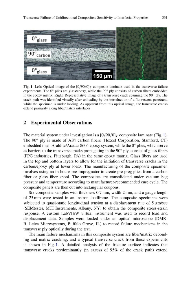
Fig. 1 Left: Optical image of the [0/90/0] T composite laminate used in the transverse failure
experiments. The 0 ◦ plies are glass/epoxy, while the 90 ◦ ply consists of carbon fibers embedded
in the epoxy matrix. Right: Representative image of a transverse crack spanning the 90 ◦ ply. The
crack path was identified visually after unloading by the introduction of a fluorescent penetrant,
while the specimen is under loading. As apparent from this optical image, the transverse cracks
extend primarily along fiber/matrix interfaces
2 Experimental Observations
The material system under investigation is a [0/90/0] T composite laminate (Fig. 1).
The 90 ◦ ply is made of AS4 carbon fibers (Hexcel Corporation, Stamford, CT)
embedded in an Araldite/Aradur 8605 epoxy system, while the 0 ◦ plies, which serve
as barriers to the transverse cracks propagating in the 90 ◦ ply, consist of glass fibers
(PPG industries, Pittsburgh, PA) in the same epoxy matrix. Glass fibers are used
in the top and bottom layers to allow for the initiation of transverse cracks in the
carbon/epoxy ply at lower loads. The manufacturing of the composite specimen
involves using an in-house pre-impregnator to create pre-preg plies from a carbon
fiber or glass fiber spool. The composites are consolidated under vacuum bag
pressure and temperature according to manufacturer-recommended cure cycle. The
composite panels are then cut into rectangular coupons.
Six composite samples with thickness 0.7 mm, width 2 mm, and a gauge length
of 25 mm were tested in an Instron loadframe. The composite specimens were
subjected to quasi-static longitudinal tension at a displacement rate of 5 μm/sec
(SEMtester, MTI Instruments, Albany, NY) to obtain the composite stress-strain
response. A custom LabVIEW virtual instrument was used to record load and
displacement data. Samples were loaded under an optical microscope (DMRR, Leica Microsystems, Buffalo Grove, IL) to record failure mechanisms in the
transverse ply optically during the test.
The main failure mechanisms in this composite system are fiber/matrix debonding and matrix cracking, and a typical transverse crack from these experiments
is shown in Fig. 1. A detailed analysis of the fracture surface indicates that
transverse cracks predominantly (in excess of 95% of the crack path) extend
331
Fig. 1 Left: Optical image of the [0/90/0] T composite laminate used in the transverse failure
experiments. The 0 ◦ plies are glass/epoxy, while the 90 ◦ ply consists of carbon fibers embedded
in the epoxy matrix. Right: Representative image of a transverse crack spanning the 90 ◦ ply. The
crack path was identified visually after unloading by the introduction of a fluorescent penetrant,
while the specimen is under loading. As apparent from this optical image, the transverse cracks
extend primarily along fiber/matrix interfaces
2 Experimental Observations
The material system under investigation is a [0/90/0] T composite laminate (Fig. 1).
The 90 ◦ ply is made of AS4 carbon fibers (Hexcel Corporation, Stamford, CT)
embedded in an Araldite/Aradur 8605 epoxy system, while the 0 ◦ plies, which serve
as barriers to the transverse cracks propagating in the 90 ◦ ply, consist of glass fibers
(PPG industries, Pittsburgh, PA) in the same epoxy matrix. Glass fibers are used
in the top and bottom layers to allow for the initiation of transverse cracks in the
carbon/epoxy ply at lower loads. The manufacturing of the composite specimen
involves using an in-house pre-impregnator to create pre-preg plies from a carbon
fiber or glass fiber spool. The composites are consolidated under vacuum bag
pressure and temperature according to manufacturer-recommended cure cycle. The
composite panels are then cut into rectangular coupons.
Six composite samples with thickness 0.7 mm, width 2 mm, and a gauge length
of 25 mm were tested in an Instron loadframe. The composite specimens were
subjected to quasi-static longitudinal tension at a displacement rate of 5 μm/sec
(SEMtester, MTI Instruments, Albany, NY) to obtain the composite stress-strain
response. A custom LabVIEW virtual instrument was used to record load and
displacement data. Samples were loaded under an optical microscope (DMRR, Leica Microsystems, Buffalo Grove, IL) to record failure mechanisms in the
transverse ply optically during the test.
The main failure mechanisms in this composite system are fiber/matrix debonding and matrix cracking, and a typical transverse crack from these experiments
is shown in Fig. 1. A detailed analysis of the fracture surface indicates that
transverse cracks predominantly (in excess of 95% of the crack path) extend