

322
S. Ghosh et al.
• The angular orientation is discretized into N θ equally spaced points of θ =
2π
N θ
.
The βth angular point is θ β = β
2π
N θ
.
• The fiber size distribution is discretized into N a equally spaced bins with a =
a max −a min
N a
, a max and a min being the maximum and minimum fiber size.
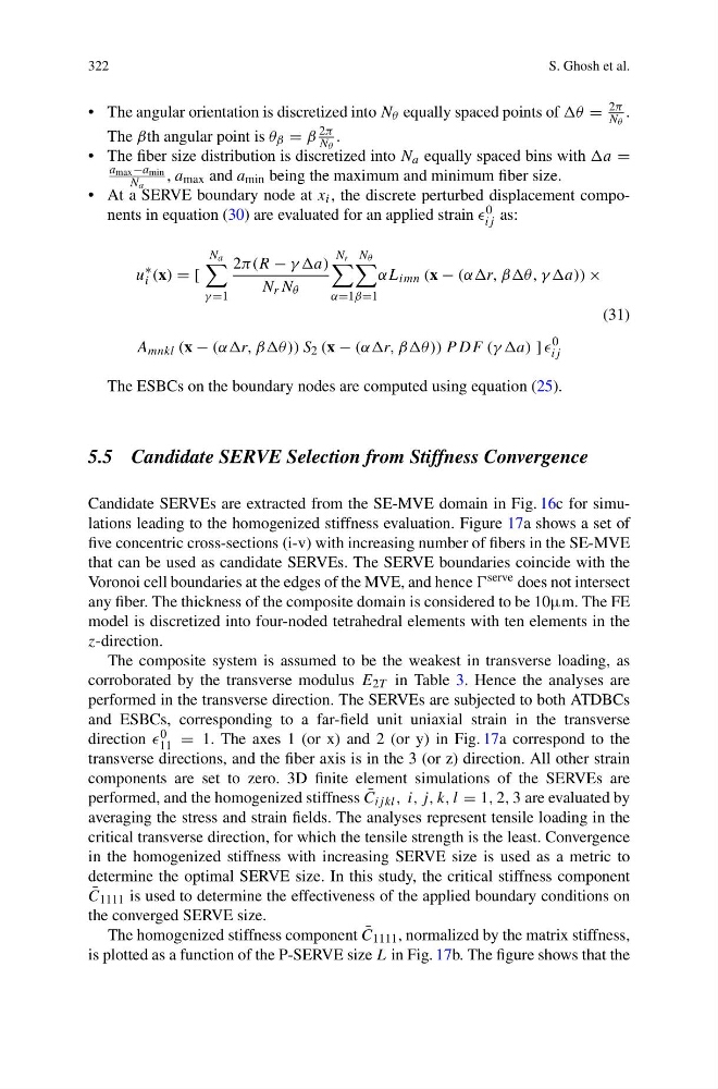
• At a SERVE boundary node at x i , the discrete perturbed displacement components in equation (30) are evaluated for an applied strain 0
ij as:
u
∗
i (x) = [
N a
γ =1
2π(R − γ γa)
N r N θ
N r
α=1
N θ
β=1
αL imn (x − (ααr, ββθ, γ γa)) ×
(31)
A mnkl (x − (ααr, ββθ )) S 2 (x − (ααr, ββθ )) P DF (γ γa) ]
0
ij
The ESBCs on the boundary nodes are computed using equation (25).
5.5 Candidate SERVE Selection from Stiffness Convergence
Candidate SERVEs are extracted from the SE-MVE domain in Fig. 16c for simulations leading to the homogenized stiffness evaluation. Figure 17a shows a set of
five concentric cross-sections (i-v) with increasing number of fibers in the SE-MVE
that can be used as candidate SERVEs. The SERVE boundaries coincide with the
Voronoi cell boundaries at the edges of the MVE, and hence serve does not intersect
any fiber. The thickness of the composite domain is considered to be 10μm. The FE
model is discretized into four-noded tetrahedral elements with ten elements in the
z-direction.
The composite system is assumed to be the weakest in transverse loading, as
corroborated by the transverse modulus E 2T in Table 3. Hence the analyses are
performed in the transverse direction. The SERVEs are subjected to both ATDBCs
and ESBCs, corresponding to a far-field unit uniaxial strain in the transverse
direction 0
11 = 1. The axes 1 (or x) and 2 (or y) in Fig. 17a correspond to the
transverse directions, and the fiber axis is in the 3 (or z) direction. All other strain
components are set to zero. 3D finite element simulations of the SERVEs are
performed, and the homogenized stiffness ¯
C ij kl , i, j, k, l = 1, 2, 3 are evaluated by
averaging the stress and strain fields. The analyses represent tensile loading in the
critical transverse direction, for which the tensile strength is the least. Convergence
in the homogenized stiffness with increasing SERVE size is used as a metric to
determine the optimal SERVE size. In this study, the critical stiffness component
¯
C 1111 is used to determine the effectiveness of the applied boundary conditions on
the converged SERVE size.
The homogenized stiffness component ¯
C 1111 , normalized by the matrix stiffness,
is plotted as a function of the P-SERVE size L in Fig. 17b. The figure shows that the
S. Ghosh et al.
• The angular orientation is discretized into N θ equally spaced points of θ =
2π
N θ
.
The βth angular point is θ β = β
2π
N θ
.
• The fiber size distribution is discretized into N a equally spaced bins with a =
a max −a min
N a
, a max and a min being the maximum and minimum fiber size.
• At a SERVE boundary node at x i , the discrete perturbed displacement components in equation (30) are evaluated for an applied strain 0
ij as:
u
∗
i (x) = [
N a
γ =1
2π(R − γ γa)
N r N θ
N r
α=1
N θ
β=1
αL imn (x − (ααr, ββθ, γ γa)) ×
(31)
A mnkl (x − (ααr, ββθ )) S 2 (x − (ααr, ββθ )) P DF (γ γa) ]
0
ij
The ESBCs on the boundary nodes are computed using equation (25).
5.5 Candidate SERVE Selection from Stiffness Convergence
Candidate SERVEs are extracted from the SE-MVE domain in Fig. 16c for simulations leading to the homogenized stiffness evaluation. Figure 17a shows a set of
five concentric cross-sections (i-v) with increasing number of fibers in the SE-MVE
that can be used as candidate SERVEs. The SERVE boundaries coincide with the
Voronoi cell boundaries at the edges of the MVE, and hence serve does not intersect
any fiber. The thickness of the composite domain is considered to be 10μm. The FE
model is discretized into four-noded tetrahedral elements with ten elements in the
z-direction.
The composite system is assumed to be the weakest in transverse loading, as
corroborated by the transverse modulus E 2T in Table 3. Hence the analyses are
performed in the transverse direction. The SERVEs are subjected to both ATDBCs
and ESBCs, corresponding to a far-field unit uniaxial strain in the transverse
direction 0
11 = 1. The axes 1 (or x) and 2 (or y) in Fig. 17a correspond to the
transverse directions, and the fiber axis is in the 3 (or z) direction. All other strain
components are set to zero. 3D finite element simulations of the SERVEs are
performed, and the homogenized stiffness ¯
C ij kl , i, j, k, l = 1, 2, 3 are evaluated by
averaging the stress and strain fields. The analyses represent tensile loading in the
critical transverse direction, for which the tensile strength is the least. Convergence
in the homogenized stiffness with increasing SERVE size is used as a metric to
determine the optimal SERVE size. In this study, the critical stiffness component
¯
C 1111 is used to determine the effectiveness of the applied boundary conditions on
the converged SERVE size.
The homogenized stiffness component ¯
C 1111 , normalized by the matrix stiffness,
is plotted as a function of the P-SERVE size L in Fig. 17b. The figure shows that the