

A Framework for Quantifying Effects of Characterization Error on the. . .
243
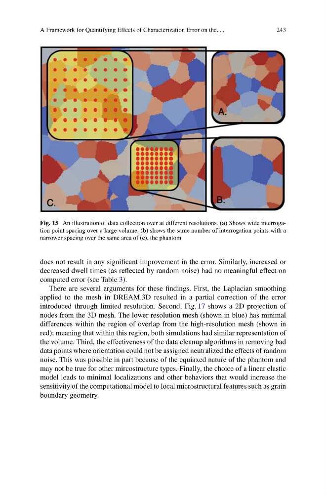
Fig. 15 An illustration of data collection over at different resolutions. (a) Shows wide interrogation point spacing over a large volume, (b) shows the same number of interrogation points with a
narrower spacing over the same area of (c), the phantom
does not result in any significant improvement in the error. Similarly, increased or
decreased dwell times (as reflected by random noise) had no meaningful effect on
computed error (see Table 3).
There are several arguments for these findings. First, the Laplacian smoothing
applied to the mesh in DREAM.3D resulted in a partial correction of the error
introduced through limited resolution. Second, Fig. 17 shows a 2D projection of
nodes from the 3D mesh. The lower resolution mesh (shown in blue) has minimal
differences within the region of overlap from the high-resolution mesh (shown in
red); meaning that within this region, both simulations had similar representation of
the volume. Third, the effectiveness of the data cleanup algorithms in removing bad
data points where orientation could not be assigned neutralized the effects of random
noise. This was possible in part because of the equiaxed nature of the phantom and
may not be true for other mircostructure types. Finally, the choice of a linear elastic
model leads to minimal localizations and other behaviors that would increase the
sensitivity of the computational model to local microstructural features such as grain
boundary geometry.
243
Fig. 15 An illustration of data collection over at different resolutions. (a) Shows wide interrogation point spacing over a large volume, (b) shows the same number of interrogation points with a
narrower spacing over the same area of (c), the phantom
does not result in any significant improvement in the error. Similarly, increased or
decreased dwell times (as reflected by random noise) had no meaningful effect on
computed error (see Table 3).
There are several arguments for these findings. First, the Laplacian smoothing
applied to the mesh in DREAM.3D resulted in a partial correction of the error
introduced through limited resolution. Second, Fig. 17 shows a 2D projection of
nodes from the 3D mesh. The lower resolution mesh (shown in blue) has minimal
differences within the region of overlap from the high-resolution mesh (shown in
red); meaning that within this region, both simulations had similar representation of
the volume. Third, the effectiveness of the data cleanup algorithms in removing bad
data points where orientation could not be assigned neutralized the effects of random
noise. This was possible in part because of the equiaxed nature of the phantom and
may not be true for other mircostructure types. Finally, the choice of a linear elastic
model leads to minimal localizations and other behaviors that would increase the
sensitivity of the computational model to local microstructural features such as grain
boundary geometry.