

212
C. A. Bronkhorst et al.
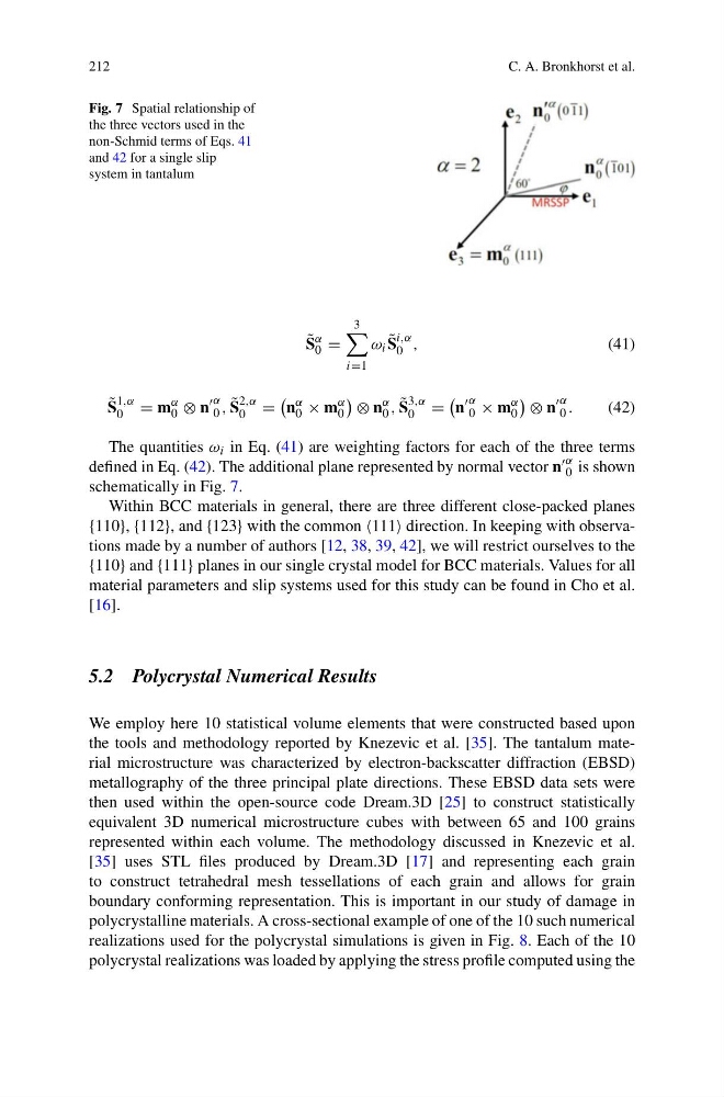
Fig. 7 Spatial relationship of
the three vectors used in the
non-Schmid terms of Eqs. 41
and 42 for a single slip
system in tantalum
˜
S
α
0 =
3
i=1
ω i ˜
S
i,α
0 ,
(41)
˜
S
1,α
0 = m
α
0 ⊗ n
α
0 , ˜
S
2,α
0 =
n
α
0 × m
α
0
⊗ n
α
0 , ˜
S
3,α
0 =
n
α
0 × m
α
0
⊗ n
α
0 .
(42)
The quantities ω i in Eq. (41) are weighting factors for each of the three terms
defined in Eq. (42). The additional plane represented by normal vector n α
0 is shown
schematically in Fig. 7.
Within BCC materials in general, there are three different close-packed planes
{110}, {112}, and {123} with the common 111 direction. In keeping with observations made by a number of authors [12, 38, 39, 42], we will restrict ourselves to the
{110} and {111} planes in our single crystal model for BCC materials. Values for all
material parameters and slip systems used for this study can be found in Cho et al.
[16].
5.2 Polycrystal Numerical Results
We employ here 10 statistical volume elements that were constructed based upon
the tools and methodology reported by Knezevic et al. [35]. The tantalum material microstructure was characterized by electron-backscatter diffraction (EBSD)
metallography of the three principal plate directions. These EBSD data sets were
then used within the open-source code Dream.3D [25] to construct statistically
equivalent 3D numerical microstructure cubes with between 65 and 100 grains
represented within each volume. The methodology discussed in Knezevic et al.
[35] uses STL files produced by Dream.3D [17] and representing each grain
to construct tetrahedral mesh tessellations of each grain and allows for grain
boundary conforming representation. This is important in our study of damage in
polycrystalline materials. A cross-sectional example of one of the 10 such numerical
realizations used for the polycrystal simulations is given in Fig. 8. Each of the 10
polycrystal realizations was loaded by applying the stress profile computed using the
C. A. Bronkhorst et al.
Fig. 7 Spatial relationship of
the three vectors used in the
non-Schmid terms of Eqs. 41
and 42 for a single slip
system in tantalum
˜
S
α
0 =
3
i=1
ω i ˜
S
i,α
0 ,
(41)
˜
S
1,α
0 = m
α
0 ⊗ n
α
0 , ˜
S
2,α
0 =
n
α
0 × m
α
0
⊗ n
α
0 , ˜
S
3,α
0 =
n
α
0 × m
α
0
⊗ n
α
0 .
(42)
The quantities ω i in Eq. (41) are weighting factors for each of the three terms
defined in Eq. (42). The additional plane represented by normal vector n α
0 is shown
schematically in Fig. 7.
Within BCC materials in general, there are three different close-packed planes
{110}, {112}, and {123} with the common 111 direction. In keeping with observations made by a number of authors [12, 38, 39, 42], we will restrict ourselves to the
{110} and {111} planes in our single crystal model for BCC materials. Values for all
material parameters and slip systems used for this study can be found in Cho et al.
[16].
5.2 Polycrystal Numerical Results
We employ here 10 statistical volume elements that were constructed based upon
the tools and methodology reported by Knezevic et al. [35]. The tantalum material microstructure was characterized by electron-backscatter diffraction (EBSD)
metallography of the three principal plate directions. These EBSD data sets were
then used within the open-source code Dream.3D [25] to construct statistically
equivalent 3D numerical microstructure cubes with between 65 and 100 grains
represented within each volume. The methodology discussed in Knezevic et al.
[35] uses STL files produced by Dream.3D [17] and representing each grain
to construct tetrahedral mesh tessellations of each grain and allows for grain
boundary conforming representation. This is important in our study of damage in
polycrystalline materials. A cross-sectional example of one of the 10 such numerical
realizations used for the polycrystal simulations is given in Fig. 8. Each of the 10
polycrystal realizations was loaded by applying the stress profile computed using the