

Local Stress and Damage Response of Polycrystal Materials to Light Shock. . .
203
of the current chapter, the results clearly indicate that pore locations are dominated
at grain boundaries within the high-purity tantalum material used in this study.
4 Macroscale Damage Modeling
The model presented here is in the long line of modified Gurson-TvergaardNeedleman [7, 26, 44]-type models for the representation of porosity-based ductile
damage. The model presented here has been adapted for application to shock
loading situations with high stress triaxiality conditions.
4.1 Damage Constitutive Model
The constitutive model used in this study is derived from the work of Addessio and
Johnson [1], Maudlin et al. [39, 40], Zou [49], and Bronkhorst et al. [10]. The model
is applied to tantalum plate impact loading as presented earlier and is summarized
here.
The Cauchy stress in the damaged state is given by
T = M ˜
T,
(1)
where the stress in the undamaged material is ˜
T and the general fourth rank isotropic
damage tensor is given by
M = (1 − φ) I,
(2)
with the scalar internal state variable φ representing the isotropic state of porosity
at the material point used in this study. In general, the tensor M allows for the
anisotropic representation of damage evolution within the material. However, for
the present study, this dependence is assumed to remain isotropic given that pores
remain close to spherical. Time integration is performed in the unrotated frame
relative to the current configuration defined by the rotation R given by the polar
decomposition
F = RU = VR.
(3)
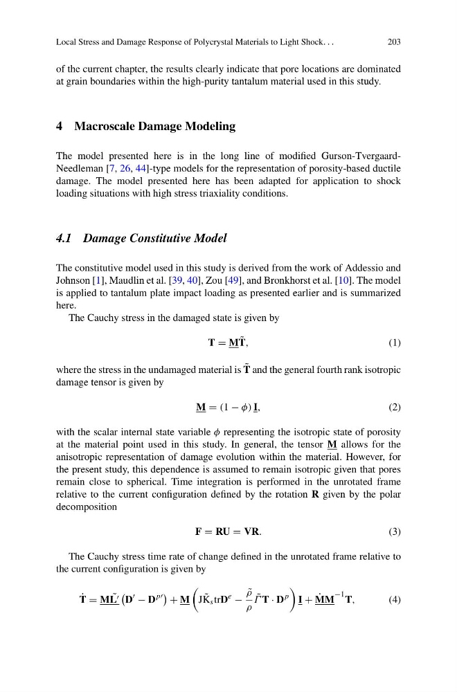
The Cauchy stress time rate of change defined in the unrotated frame relative to
the current configuration is given by
˙
T = M ˜
L
D
− D
p
+ M
J ˜
K s trD
e
−
˜
ρ
ρ
˜
Γ T · D
p
I + ˙
MM
−1 T,
(4)
203
of the current chapter, the results clearly indicate that pore locations are dominated
at grain boundaries within the high-purity tantalum material used in this study.
4 Macroscale Damage Modeling
The model presented here is in the long line of modified Gurson-TvergaardNeedleman [7, 26, 44]-type models for the representation of porosity-based ductile
damage. The model presented here has been adapted for application to shock
loading situations with high stress triaxiality conditions.
4.1 Damage Constitutive Model
The constitutive model used in this study is derived from the work of Addessio and
Johnson [1], Maudlin et al. [39, 40], Zou [49], and Bronkhorst et al. [10]. The model
is applied to tantalum plate impact loading as presented earlier and is summarized
here.
The Cauchy stress in the damaged state is given by
T = M ˜
T,
(1)
where the stress in the undamaged material is ˜
T and the general fourth rank isotropic
damage tensor is given by
M = (1 − φ) I,
(2)
with the scalar internal state variable φ representing the isotropic state of porosity
at the material point used in this study. In general, the tensor M allows for the
anisotropic representation of damage evolution within the material. However, for
the present study, this dependence is assumed to remain isotropic given that pores
remain close to spherical. Time integration is performed in the unrotated frame
relative to the current configuration defined by the rotation R given by the polar
decomposition
F = RU = VR.
(3)
The Cauchy stress time rate of change defined in the unrotated frame relative to
the current configuration is given by
˙
T = M ˜
L
D
− D
p
+ M
J ˜
K s trD
e
−
˜
ρ
ρ
˜
Γ T · D
p
I + ˙
MM
−1 T,
(4)