

104
D. W. Eastman et al.
that will be eventually used for ablation of the target material. The maximum output
of the laser is 1 W, but the actual power used in machining is 0.1 W or less and can
be controlled from the main laser system console. The laser beam is directed into
a custom built safety enclosure, where the laser optics and machining components
reside. The beam first passes through a waveplate polarizer, which allows for more
precise attenuation of the beam as well as the ability to automate the attenuation
process. A software interface on the system computer allows for precise rotation
of the waveplate to carefully control the laser energy. The beam is then directed
within the containment using a series of laser steering mirrors that reflect it to a final
dichroic mirror. A dichroic mirror reflects the beam downward to a 10x Mitutoyo
NIR objective lens, which focuses the beam to a spot size of about 30 μm for
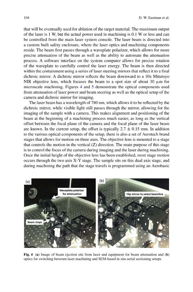
microscale machining. Figures 4 and 5 demonstrate the optical components used
from attenuation of laser power and beam steering as well as the optical setup of the
camera and dichroic mirror for imaging.
The laser beam has a wavelength of 780 nm, which allows it to be reflected by the
dichroic mirror, while visible light still passes through the mirror, allowing for the
imaging of the sample with a camera. This makes alignment and positioning of the
beam at the beginning of a machining process much easier, as long as the vertical
offset between the focal plane of the camera and the focal plane of the laser beam
are known. In the current setup, the offset is typically 2.7 ± 0.15 mm. In addition
to the various optical components of the setup, there is also a set of Aerotech brand
stages that allows for motion on three axes. The objective lens is mounted to a stage
that controls the motion in the vertical (Z) direction. The main purpose of this stage
is to control the focus of the camera during imaging and the laser during machining.
Once the initial height of the objective lens has been established, most stage motion
occurs through the two axis X-Y stage. The sample sits on this dual axis stage, and
during machining the path that the stage travels is programmed using an Aerobasic
Fig. 4 (a) Image of beam ejection site from laser and equipment for beam attenuation and (b)
optics for switching between laser machining and SEM-based in situ serial sectioning setups
D. W. Eastman et al.
that will be eventually used for ablation of the target material. The maximum output
of the laser is 1 W, but the actual power used in machining is 0.1 W or less and can
be controlled from the main laser system console. The laser beam is directed into
a custom built safety enclosure, where the laser optics and machining components
reside. The beam first passes through a waveplate polarizer, which allows for more
precise attenuation of the beam as well as the ability to automate the attenuation
process. A software interface on the system computer allows for precise rotation
of the waveplate to carefully control the laser energy. The beam is then directed
within the containment using a series of laser steering mirrors that reflect it to a final
dichroic mirror. A dichroic mirror reflects the beam downward to a 10x Mitutoyo
NIR objective lens, which focuses the beam to a spot size of about 30 μm for
microscale machining. Figures 4 and 5 demonstrate the optical components used
from attenuation of laser power and beam steering as well as the optical setup of the
camera and dichroic mirror for imaging.
The laser beam has a wavelength of 780 nm, which allows it to be reflected by the
dichroic mirror, while visible light still passes through the mirror, allowing for the
imaging of the sample with a camera. This makes alignment and positioning of the
beam at the beginning of a machining process much easier, as long as the vertical
offset between the focal plane of the camera and the focal plane of the laser beam
are known. In the current setup, the offset is typically 2.7 ± 0.15 mm. In addition
to the various optical components of the setup, there is also a set of Aerotech brand
stages that allows for motion on three axes. The objective lens is mounted to a stage
that controls the motion in the vertical (Z) direction. The main purpose of this stage
is to control the focus of the camera during imaging and the laser during machining.
Once the initial height of the objective lens has been established, most stage motion
occurs through the two axis X-Y stage. The sample sits on this dual axis stage, and
during machining the path that the stage travels is programmed using an Aerobasic
Fig. 4 (a) Image of beam ejection site from laser and equipment for beam attenuation and (b)
optics for switching between laser machining and SEM-based in situ serial sectioning setups