

67
Review of Basic Device Physics
Actual diodes may represent intermediate cases, that is, W n > L p and W p < L n
and vice versa. In either case, the lightly doped side of the junction largely
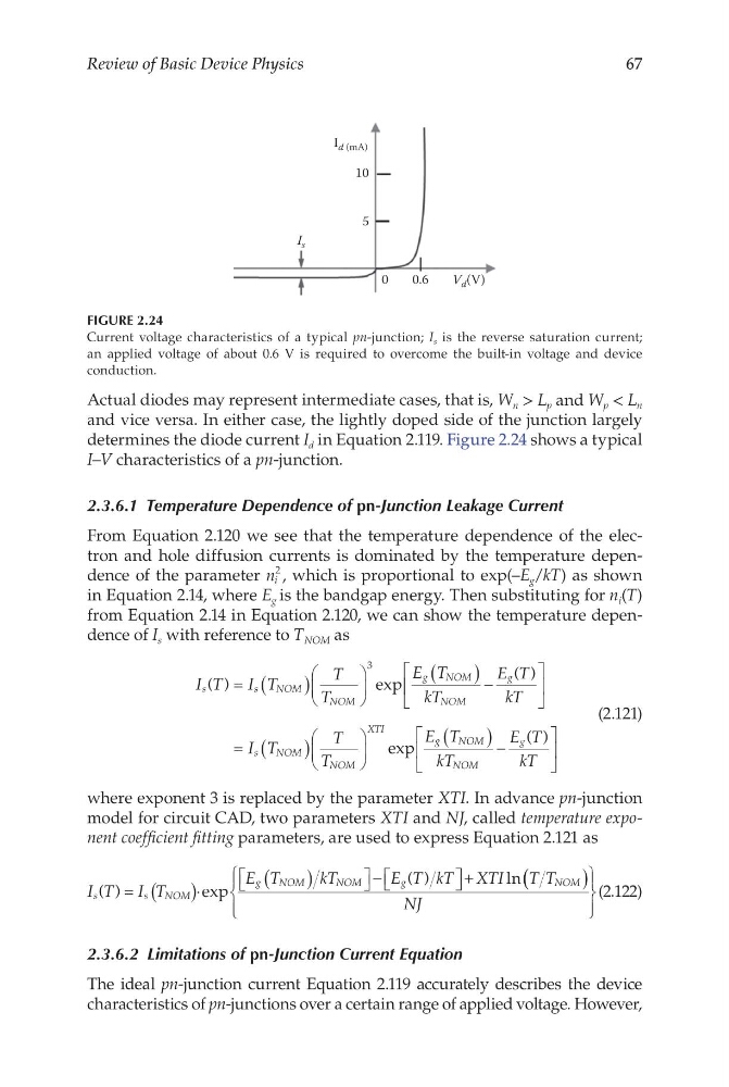
determines the diode current I d in Equation 2.119. Figure 2.24 shows a typical
I–V characteristics of a pn-junction.
2.3.6.1 Temperature Dependence of pn-Junction Leakage Current
From Equation 2.120 we see that the temperature dependence of the electron and hole diffusion currents is dominated by the temperature dependence of the parameter n i
2 , which is proportional to exp(–E g /kT) as shown
in Equation 2.14, where E g is the bandgap energy. Then substituting for n i (T)
from Equation 2.14 in Equation 2.120, we can show the temperature dependence of I s with reference to T NOM as
I T
I T
T
T
E T
kT
E T
kT
s
s
NOM
NOM
g
NOM
NOM
g
( )
exp
( )
= (
)
(
) −
3
= (
)
(
) −
I T
T
T
E T
kT
E T
kT
s
NOM
NOM
XTI
g
NOM
NOM
g
exp
( )
(2.121)
where exponent 3 is replaced by the parameter XTI. In advance pn-junction
model for circuit CAD, two parameters XTI and NJ, called temperature exponent coefficient fitting parameters, are used to express Equation 2.121 as
I T I T
E T
kT
E T kT XTI
T T
s
s
NOM
g
NOM
NOM
g
NOM
( )
exp
( )
ln
= (
)⋅
(
)
−
+
( (
)
NJ
(2.122)
2.3.6.2 Limitations of pn-Junction Current Equation
The ideal pn-junction current Equation 2.119 accurately describes the device
characteristics of pn-junctions over a certain range of applied voltage. However,
0
5
I s
10
I d (mA)
0.6
V d (V)
FIGURE 2.24
Current voltage characteristics of a typical pn-junction; I s is the reverse saturation current;
an applied voltage of about 0.6 V is required to overcome the built-in voltage and device
conduction.
Review of Basic Device Physics
Actual diodes may represent intermediate cases, that is, W n > L p and W p < L n
and vice versa. In either case, the lightly doped side of the junction largely
determines the diode current I d in Equation 2.119. Figure 2.24 shows a typical
I–V characteristics of a pn-junction.
2.3.6.1 Temperature Dependence of pn-Junction Leakage Current
From Equation 2.120 we see that the temperature dependence of the electron and hole diffusion currents is dominated by the temperature dependence of the parameter n i
2 , which is proportional to exp(–E g /kT) as shown
in Equation 2.14, where E g is the bandgap energy. Then substituting for n i (T)
from Equation 2.14 in Equation 2.120, we can show the temperature dependence of I s with reference to T NOM as
I T
I T
T
T
E T
kT
E T
kT
s
s
NOM
NOM
g
NOM
NOM
g
( )
exp
( )
= (
)
(
) −
3
= (
)
(
) −
I T
T
T
E T
kT
E T
kT
s
NOM
NOM
XTI
g
NOM
NOM
g
exp
( )
(2.121)
where exponent 3 is replaced by the parameter XTI. In advance pn-junction
model for circuit CAD, two parameters XTI and NJ, called temperature exponent coefficient fitting parameters, are used to express Equation 2.121 as
I T I T
E T
kT
E T kT XTI
T T
s
s
NOM
g
NOM
NOM
g
NOM
( )
exp
( )
ln
= (
)⋅
(
)
−
+
( (
)
NJ
(2.122)
2.3.6.2 Limitations of pn-Junction Current Equation
The ideal pn-junction current Equation 2.119 accurately describes the device
characteristics of pn-junctions over a certain range of applied voltage. However,
0
5
I s
10
I d (mA)
0.6
V d (V)
FIGURE 2.24
Current voltage characteristics of a typical pn-junction; I s is the reverse saturation current;
an applied voltage of about 0.6 V is required to overcome the built-in voltage and device
conduction.