

66
Compact Models for Integrated Circuit Design
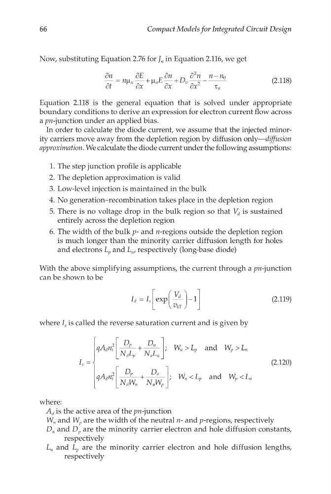
Now, substituting Equation 2.76 for J n in Equation 2.116, we get
∂
∂
=
∂
∂
+
∂
∂
+
∂
∂
−
−
n
t
n
E
x
E
n
x
D
n
x
n n
n
n
n
n
µ
µ
τ
2
2
0
(2.118)
Equation 2.118 is the general equation that is solved under appropriate
boundary conditions to derive an expression for electron current flow across
a pn-junction under an applied bias.
In order to calculate the diode current, we assume that the injected minority carriers move away from the depletion region by diffusion only—diffusion
approximation. We calculate the diode current under the following assumptions:
1. The step junction profile is applicable
2. The depletion approximation is valid
3. Low-level injection is maintained in the bulk
4. No generation–recombination takes place in the depletion region
5. There is no voltage drop in the bulk region so that V d is sustained
entirely across the depletion region
6. The width of the bulk p- and n-regions outside the depletion region
is much longer than the minority carrier diffusion length for holes
and electrons L p and L n , respectively (long-base diode)
With the above simplifying assumptions, the current through a pn-junction
can be shown to be
I
I
V
v
d
s
d
kT
=
−
exp
1
(2.119)
where I s is called the reverse saturation current and is given by
I
qA n
D
N L
D
N L
W L
W L
qA n
D
N W
D
N
s
d i
p
d p
n
a n
n
p
p
n
d i
p
d n
n
=
+
>
>
+
2
2
;
a nd
a a p
n
p
p
n
W
W L
W L
<
<
;
a nd
(2.120)
where:
A d is the active area of the pn-junction
W n and W p are the width of the neutral n- and p-regions, respectively
D n and D p are the minority carrier electron and hole diffusion constants,
respectively
L n and L p are the minority carrier electron and hole diffusion lengths,
respectively
Compact Models for Integrated Circuit Design
Now, substituting Equation 2.76 for J n in Equation 2.116, we get
∂
∂
=
∂
∂
+
∂
∂
+
∂
∂
−
−
n
t
n
E
x
E
n
x
D
n
x
n n
n
n
n
n
µ
µ
τ
2
2
0
(2.118)
Equation 2.118 is the general equation that is solved under appropriate
boundary conditions to derive an expression for electron current flow across
a pn-junction under an applied bias.
In order to calculate the diode current, we assume that the injected minority carriers move away from the depletion region by diffusion only—diffusion
approximation. We calculate the diode current under the following assumptions:
1. The step junction profile is applicable
2. The depletion approximation is valid
3. Low-level injection is maintained in the bulk
4. No generation–recombination takes place in the depletion region
5. There is no voltage drop in the bulk region so that V d is sustained
entirely across the depletion region
6. The width of the bulk p- and n-regions outside the depletion region
is much longer than the minority carrier diffusion length for holes
and electrons L p and L n , respectively (long-base diode)
With the above simplifying assumptions, the current through a pn-junction
can be shown to be
I
I
V
v
d
s
d
kT
=
−
exp
1
(2.119)
where I s is called the reverse saturation current and is given by
I
qA n
D
N L
D
N L
W L
W L
qA n
D
N W
D
N
s
d i
p
d p
n
a n
n
p
p
n
d i
p
d n
n
=
+
>
>
+
2
2
;
a nd
a a p
n
p
p
n
W
W L
W L
<
<
;
a nd
(2.120)
where:
A d is the active area of the pn-junction
W n and W p are the width of the neutral n- and p-regions, respectively
D n and D p are the minority carrier electron and hole diffusion constants,
respectively
L n and L p are the minority carrier electron and hole diffusion lengths,
respectively