

433
Compact Model Library for Circuit Simulation
delta is the 3σ variation of the mean value of the corresponding parameter;
where σ is the variance of the statistical distribution of the model parameter.
Let us consider a typical parameter file of a standard V th (svt) device of a
CMOS technology. A typical parameter is then parameterized in the model
card as: TT ± delta. Thus, the model parameter VTH0 is parameterized for
SS and FF corners as
VTH
VTH
0
0
=
±dvthn svt
_
(12.1)
where:
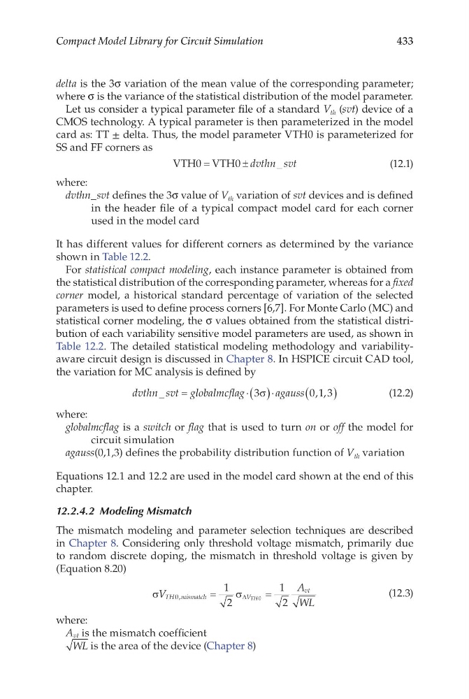
dvthn_svt defines the 3σ value of V th variation of svt devices and is defined
in the header file of a typical compact model card for each corner
used in the model card
It has different values for different corners as determined by the variance
shown in Table 12.2.
For statistical compact modeling, each instance parameter is obtained from
the statistical distribution of the corresponding parameter, whereas for a fixed
corner model, a historical standard percentage of variation of the selected
parameters is used to define process corners [6,7]. For Monte Carlo (MC) and
statistical corner modeling, the σ values obtained from the statistical distribution of each variability sensitive model parameters are used, as shown in
Table 12.2. The detailed statistical modeling methodology and variabilityaware circuit design is discussed in Chapter 8. In HSPICE circuit CAD tool,
the variation for MC analysis is defined by
dvthn svt globalmcflag
agauss
_
, ,
=
⋅
⋅
( )
(
)
3
01 3
σ
(12.2)
where:
globalmcflag is a switch or flag that is used to turn on or off the model for
circuit simulation
agauss(0,1,3) defines the probability distribution function of V th variation
Equations 12.1 and 12.2 are used in the model card shown at the end of this
chapter.
12.2.4.2 Modeling Mismatch
The mismatch modeling and parameter selection techniques are described
in Chapter 8. Considering only threshold voltage mismatch, primarily due
to ran dom discrete doping, the mismatch in threshold voltage is given by
(Equation 8.20)
σ
σ
V
A
WL
TH mismatch
V
vt
TH
0
1
2
1
2
0
,
=
=
∆
(12.3)
where:
A vt is the mismatch coefficient
WL is the area of the device (Chapter 8)
Compact Model Library for Circuit Simulation
delta is the 3σ variation of the mean value of the corresponding parameter;
where σ is the variance of the statistical distribution of the model parameter.
Let us consider a typical parameter file of a standard V th (svt) device of a
CMOS technology. A typical parameter is then parameterized in the model
card as: TT ± delta. Thus, the model parameter VTH0 is parameterized for
SS and FF corners as
VTH
VTH
0
0
=
±dvthn svt
_
(12.1)
where:
dvthn_svt defines the 3σ value of V th variation of svt devices and is defined
in the header file of a typical compact model card for each corner
used in the model card
It has different values for different corners as determined by the variance
shown in Table 12.2.
For statistical compact modeling, each instance parameter is obtained from
the statistical distribution of the corresponding parameter, whereas for a fixed
corner model, a historical standard percentage of variation of the selected
parameters is used to define process corners [6,7]. For Monte Carlo (MC) and
statistical corner modeling, the σ values obtained from the statistical distribution of each variability sensitive model parameters are used, as shown in
Table 12.2. The detailed statistical modeling methodology and variabilityaware circuit design is discussed in Chapter 8. In HSPICE circuit CAD tool,
the variation for MC analysis is defined by
dvthn svt globalmcflag
agauss
_
, ,
=
⋅
⋅
( )
(
)
3
01 3
σ
(12.2)
where:
globalmcflag is a switch or flag that is used to turn on or off the model for
circuit simulation
agauss(0,1,3) defines the probability distribution function of V th variation
Equations 12.1 and 12.2 are used in the model card shown at the end of this
chapter.
12.2.4.2 Modeling Mismatch
The mismatch modeling and parameter selection techniques are described
in Chapter 8. Considering only threshold voltage mismatch, primarily due
to ran dom discrete doping, the mismatch in threshold voltage is given by
(Equation 8.20)
σ
σ
V
A
WL
TH mismatch
V
vt
TH
0
1
2
1
2
0
,
=
=
∆
(12.3)
where:
A vt is the mismatch coefficient
WL is the area of the device (Chapter 8)