

416
Compact Models for Integrated Circuit Design
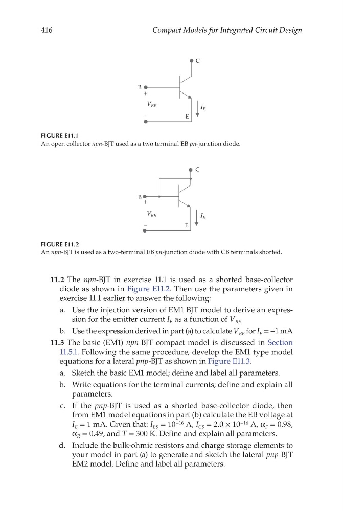
11.2 The npn-BJT in exercise 11.1 is used as a shorted base-collector
diode as shown in Figure E11.2. Then use the parameters given in
exercise 11.1 earlier to answer the following:
a. Use the injection version of EM1 BJT model to derive an expression for the emitter current I E as a function of V BE
b. Use the expression derived in part (a) to calculate V BE for I E = −1 mA
11.3 The basic (EM1) npn-BJT compact model is discussed in Section
11.5.1. Following the same procedure, develop the EM1 type model
equations for a lateral pnp-BJT as shown in Figure E11.3.
a. Sketch the basic EM1 model; define and label all parameters.
b. Write equations for the terminal currents; define and explain all
parameters.
c. If the pnp-BJT is used as a shorted base-collector diode, then
from EM1 model equations in part (b) calculate the EB voltage at
I E = 1 mA. Given that: I ES = 10 −16 A, I CS = 2.0 × 10 −16 A, α F = 0.98,
α R = 0.49, and T = 300 K. Define and explain all parameters.
d. Include the bulk-ohmic resistors and charge storage elements to
your model in part (a) to generate and sketch the lateral pnp-BJT
EM2 model. Define and label all parameters.
C
E
B +
−
I E
V BE
FIGURE E11.1
An open collector npn-BJT used as a two terminal EB pn-junction diode.
C
E
B +
−
I E
V BE
FIGURE E11.2
An npn-BJT is used as a two-terminal EB pn-junction diode with CB terminals shorted.
Compact Models for Integrated Circuit Design
11.2 The npn-BJT in exercise 11.1 is used as a shorted base-collector
diode as shown in Figure E11.2. Then use the parameters given in
exercise 11.1 earlier to answer the following:
a. Use the injection version of EM1 BJT model to derive an expression for the emitter current I E as a function of V BE
b. Use the expression derived in part (a) to calculate V BE for I E = −1 mA
11.3 The basic (EM1) npn-BJT compact model is discussed in Section
11.5.1. Following the same procedure, develop the EM1 type model
equations for a lateral pnp-BJT as shown in Figure E11.3.
a. Sketch the basic EM1 model; define and label all parameters.
b. Write equations for the terminal currents; define and explain all
parameters.
c. If the pnp-BJT is used as a shorted base-collector diode, then
from EM1 model equations in part (b) calculate the EB voltage at
I E = 1 mA. Given that: I ES = 10 −16 A, I CS = 2.0 × 10 −16 A, α F = 0.98,
α R = 0.49, and T = 300 K. Define and explain all parameters.
d. Include the bulk-ohmic resistors and charge storage elements to
your model in part (a) to generate and sketch the lateral pnp-BJT
EM2 model. Define and label all parameters.
C
E
B +
−
I E
V BE
FIGURE E11.1
An open collector npn-BJT used as a two terminal EB pn-junction diode.
C
E
B +
−
I E
V BE
FIGURE E11.2
An npn-BJT is used as a two-terminal EB pn-junction diode with CB terminals shorted.