

400
Compact Models for Integrated Circuit Design
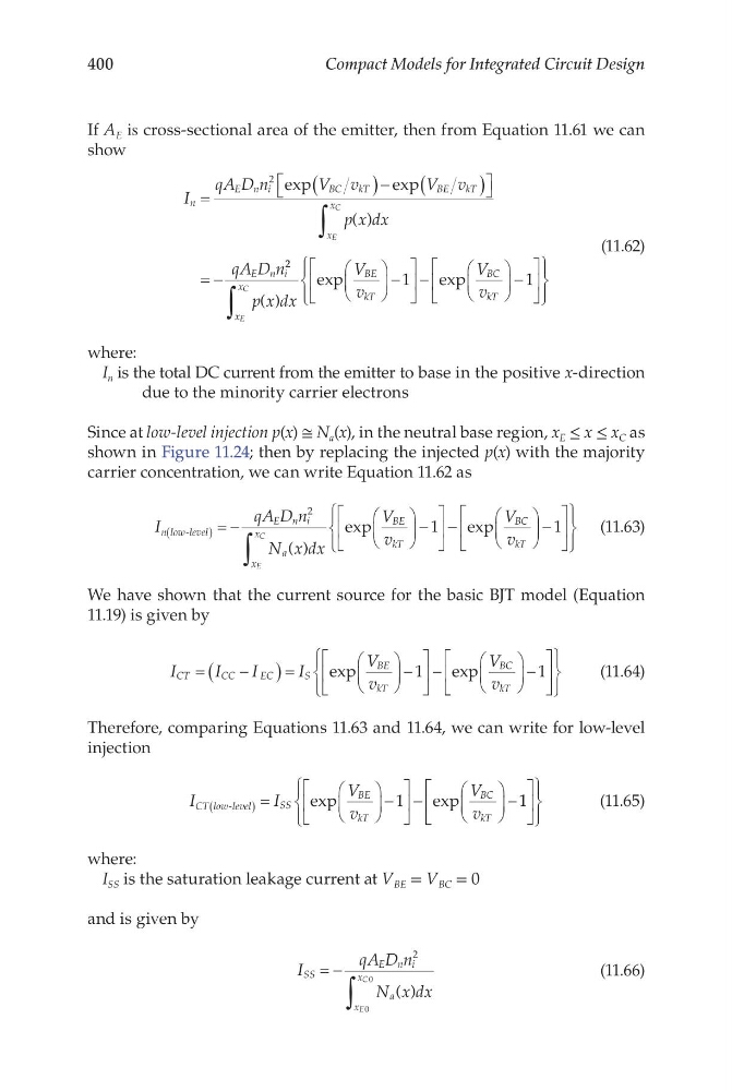
If A E is cross-sectional area of the emitter, then from Equation 11.61 we can
show
I
qA D n
V v
V v
p x dx
qA D n
n
E n i
B C
kT
B E
kT
x
x
E n i
E
C
=
(
)− (
)
= −
∫
2 exp
e xp
( )
2 2
1
1
p x dx
V
v
V
v
x
x
BE
kT
BC
kT
E
C ( )
exp
e xp
∫
−
−
−
(11.62)
where:
I n is the total DC current from the emitter to base in the positive x-direction
due to the minority carrier electrons
Since at low-level injection p(x) ≅ N a (x), in the neutral base region, x E ≤ x ≤ x C as
shown in Figure 11.24; then by replacing the injected p(x) with the majority
carrier concentration, we can write Equation 11.62 as
I
qA D n
N x dx
V
v
n low level
E n i
a
x
x
BE
kT
E
C
-
( )
exp
(
) = −
−
∫
2
1 − −
−
exp
V
v
BC
kT
1
(11.63)
We have shown that the current source for the basic BJT model (Equation
11.19) is given by
I
I
I
I
V
v
V
v
CT
CC
EC
S
BE
kT
BC
kT
=
−
(
)=
−
−
−
exp
e xp
1
1
(11.64)
Therefore, comparing Equations 11.63 and 11.64, we can write for low-level
injection
I
I
V
v
V
v
CT low level
SS
BE
kT
BC
kT
-
exp
e xp
(
) =
−
−
−
1
1
1
(11.65)
where:
I SS is the saturation leakage current at V BE = V BC = 0
and is given by
I
qA D n
N x dx
SS
E n i
a
x
x
E
C
= − ∫
2
0
0
( )
(11.66)
Compact Models for Integrated Circuit Design
If A E is cross-sectional area of the emitter, then from Equation 11.61 we can
show
I
qA D n
V v
V v
p x dx
qA D n
n
E n i
B C
kT
B E
kT
x
x
E n i
E
C
=
(
)− (
)
= −
∫
2 exp
e xp
( )
2 2
1
1
p x dx
V
v
V
v
x
x
BE
kT
BC
kT
E
C ( )
exp
e xp
∫
−
−
−
(11.62)
where:
I n is the total DC current from the emitter to base in the positive x-direction
due to the minority carrier electrons
Since at low-level injection p(x) ≅ N a (x), in the neutral base region, x E ≤ x ≤ x C as
shown in Figure 11.24; then by replacing the injected p(x) with the majority
carrier concentration, we can write Equation 11.62 as
I
qA D n
N x dx
V
v
n low level
E n i
a
x
x
BE
kT
E
C
-
( )
exp
(
) = −
−
∫
2
1 − −
−
exp
V
v
BC
kT
1
(11.63)
We have shown that the current source for the basic BJT model (Equation
11.19) is given by
I
I
I
I
V
v
V
v
CT
CC
EC
S
BE
kT
BC
kT
=
−
(
)=
−
−
−
exp
e xp
1
1
(11.64)
Therefore, comparing Equations 11.63 and 11.64, we can write for low-level
injection
I
I
V
v
V
v
CT low level
SS
BE
kT
BC
kT
-
exp
e xp
(
) =
−
−
−
1
1
1
(11.65)
where:
I SS is the saturation leakage current at V BE = V BC = 0
and is given by
I
qA D n
N x dx
SS
E n i
a
x
x
E
C
= − ∫
2
0
0
( )
(11.66)