

392
Compact Models for Integrated Circuit Design
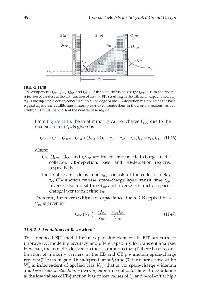
From Figure 11.18, the total minority carrier charge Q DC due to the
reverse current I EC is given by
Q
Q Q
Q
Q
I
I
DC
C
B CR
BR
BER
C
C B
B R
E B EC
R dc EC
=
+
+
+
=
+
+
+
=
(
)
τ τ
τ
τ
τ
(11.46)
where:
Q C , Q BCR , Q BR , and Q BER are the reverse-injected charge in the
collector, CB-depletion, base, and EB-depletion regions,
respectively
the total reverse delay time τ Rdc consists of the collector delay
τ C , CB-junction reverse space-charge layer transit time τ CB ,
reverse base transit time τ BR , and reverse EB-junction spacecharge layer transit time τ EB
Therefore, the reverse diffusion capacitance due to CB applied bias
V BC is given by
C V
Q
V
I
V
DC
DC
B C
Rdc EC
B C
BC
( )=
=
′ ′
′ ′
τ
(11.47)
11.5.2.2 Limitations of Basic Model
The enhanced BJT model includes parasitic elements in BJT structure to
improve DC modeling accuracy and offers capability for transient analysis.
However, the model is derived on the assumptions that (1) there is no recombination of minority carriers in the EB and CB pn-junction space-charge
regions; (2) current gain β is independent of I C ; and (3) the neutral base width
W B is independent of applied bias V BC , that is, no space-charge widening
and base-width modulation. However, experimental data show β-degradation
at the low values of EB-junction bias or low values of I C , and β-roll-off at high
C (n)
B (p)
E (n+)
W B
Q BER
Q BCR
Q BR
Q C
n pR
n p0
p n 0
p n 0
FIGURE 11.18
The components Q C , Q BCR , Q BR , and Q BER of the total diffusion charge Q DC due to the reverse
injection of carriers at the CB-junction of an npn-BJT resulting in the diffusion capacitance, C DC ;
n pR is the injected electron concentration at the edge of the CB-depletion region inside the base;
p n0 and n p0 are the equilibrium minority carrier concentrations in the n and p regions, respectively; and W B is the width of the neutral base region.
Compact Models for Integrated Circuit Design
From Figure 11.18, the total minority carrier charge Q DC due to the
reverse current I EC is given by
Q
Q Q
Q
Q
I
I
DC
C
B CR
BR
BER
C
C B
B R
E B EC
R dc EC
=
+
+
+
=
+
+
+
=
(
)
τ τ
τ
τ
τ
(11.46)
where:
Q C , Q BCR , Q BR , and Q BER are the reverse-injected charge in the
collector, CB-depletion, base, and EB-depletion regions,
respectively
the total reverse delay time τ Rdc consists of the collector delay
τ C , CB-junction reverse space-charge layer transit time τ CB ,
reverse base transit time τ BR , and reverse EB-junction spacecharge layer transit time τ EB
Therefore, the reverse diffusion capacitance due to CB applied bias
V BC is given by
C V
Q
V
I
V
DC
DC
B C
Rdc EC
B C
BC
( )=
=
′ ′
′ ′
τ
(11.47)
11.5.2.2 Limitations of Basic Model
The enhanced BJT model includes parasitic elements in BJT structure to
improve DC modeling accuracy and offers capability for transient analysis.
However, the model is derived on the assumptions that (1) there is no recombination of minority carriers in the EB and CB pn-junction space-charge
regions; (2) current gain β is independent of I C ; and (3) the neutral base width
W B is independent of applied bias V BC , that is, no space-charge widening
and base-width modulation. However, experimental data show β-degradation
at the low values of EB-junction bias or low values of I C , and β-roll-off at high
C (n)
B (p)
E (n+)
W B
Q BER
Q BCR
Q BR
Q C
n pR
n p0
p n 0
p n 0
FIGURE 11.18
The components Q C , Q BCR , Q BR , and Q BER of the total diffusion charge Q DC due to the reverse
injection of carriers at the CB-junction of an npn-BJT resulting in the diffusion capacitance, C DC ;
n pR is the injected electron concentration at the edge of the CB-depletion region inside the base;
p n0 and n p0 are the equilibrium minority carrier concentrations in the n and p regions, respectively; and W B is the width of the neutral base region.