

380
Compact Models for Integrated Circuit Design
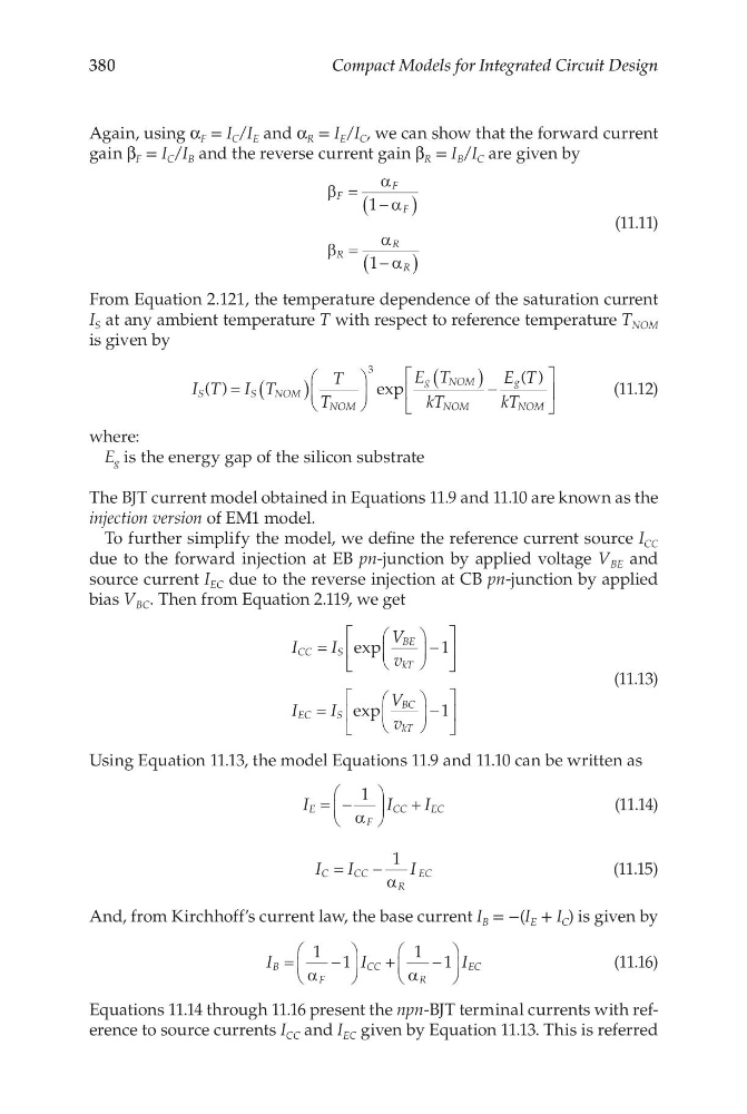
Again, using α F = I C /I E and α R = I E /I C , we can show that the forward current
gain β F = I C /I B and the reverse current gain β R = I B /I C are given by
β
α
α
β
α
α
F
F
F
R
R
R
= −
(
)
= −
(
)
1
1
(11.11)
From Equation 2.121, the temperature dependence of the saturation current
I S at any ambient temperature T with respect to reference temperature T NOM
is given by
I T I T
T
T
E T
kT
E T
kT
NOM
NOM
g
NOM
NOM
g
NOM
S
S
( )
exp
( )
= (
)
(
) −
3
(11.12)
where:
E g is the energy gap of the silicon substrate
The BJT current model obtained in Equations 11.9 and 11.10 are known as the
injection version of EM1 model.
To further simplify the model, we define the reference current source I CC
due to the forward injection at EB pn-junction by applied voltage V BE and
source current I EC due to the reverse injection at CB pn-junction by applied
bias V BC . Then from Equation 2.119, we get
I
I
V
v
I
I
V
v
CC
S
BE
kT
EC
S
BC
kT
=
−
=
−
exp
exp
1
1
(11.13)
Using Equation 11.13, the model Equations 11.9 and 11.10 can be written as
I
I
I
E
F
CC
EC
= −
+
1
α
(11.14)
I
I
I
C
C C
R
EC
=
−
1
α
(11.15)
And, from Kirchhoff’s current law, the base current I B = −(I E + I C ) is given by
I
I
I
B
F
CC
R
EC
=
−
+
−
1 1
1 1
α
α
(11.16)
Equations 11.14 through 11.16 present the npn-BJT terminal currents with reference to source currents I CC and I EC given by Equation 11.13. This is referred
Compact Models for Integrated Circuit Design
Again, using α F = I C /I E and α R = I E /I C , we can show that the forward current
gain β F = I C /I B and the reverse current gain β R = I B /I C are given by
β
α
α
β
α
α
F
F
F
R
R
R
= −
(
)
= −
(
)
1
1
(11.11)
From Equation 2.121, the temperature dependence of the saturation current
I S at any ambient temperature T with respect to reference temperature T NOM
is given by
I T I T
T
T
E T
kT
E T
kT
NOM
NOM
g
NOM
NOM
g
NOM
S
S
( )
exp
( )
= (
)
(
) −
3
(11.12)
where:
E g is the energy gap of the silicon substrate
The BJT current model obtained in Equations 11.9 and 11.10 are known as the
injection version of EM1 model.
To further simplify the model, we define the reference current source I CC
due to the forward injection at EB pn-junction by applied voltage V BE and
source current I EC due to the reverse injection at CB pn-junction by applied
bias V BC . Then from Equation 2.119, we get
I
I
V
v
I
I
V
v
CC
S
BE
kT
EC
S
BC
kT
=
−
=
−
exp
exp
1
1
(11.13)
Using Equation 11.13, the model Equations 11.9 and 11.10 can be written as
I
I
I
E
F
CC
EC
= −
+
1
α
(11.14)
I
I
I
C
C C
R
EC
=
−
1
α
(11.15)
And, from Kirchhoff’s current law, the base current I B = −(I E + I C ) is given by
I
I
I
B
F
CC
R
EC
=
−
+
−
1 1
1 1
α
α
(11.16)
Equations 11.14 through 11.16 present the npn-BJT terminal currents with reference to source currents I CC and I EC given by Equation 11.13. This is referred