

333
Compact Models for Ultrathin Body FETs
9.4.1 Electrostatics
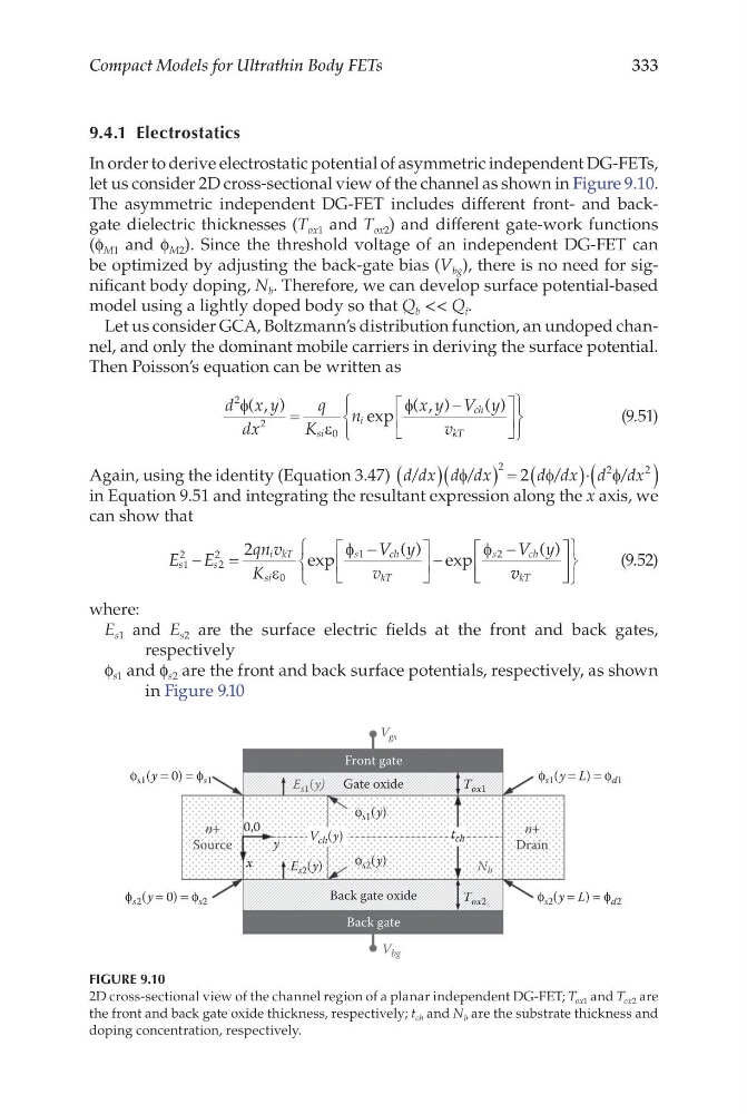
In order to derive electrostatic potential of asymmetric independent DG-FETs,
let us consider 2D cross-sectional view of the channel as shown in Figure 9.10.
The asymmetric independent DG-FET includes different front- and backgate dielectric thicknesses (T ox1 and T ox2 ) and different gate-work functions
(f M1 and f M2 ). Since the threshold voltage of an independent DG-FET can
be optimized by adjusting the back-gate bias (V bg ), there is no need for significant body doping, N b . Therefore, we can develop surface potential-based
model using a lightly doped body so that Q b << Q i .
Let us consider GCA, Boltzmann’s distribution function, an undoped channel, and only the dominant mobile carriers in deriving the surface potential.
Then Poisson’s equation can be written as
d x y
dx
q
K
n
x y V y
v
si
i
ch
kT
2
2
0
φ
ε
φ
( , )
exp
( , )
( )
=
−
(9.51)
Again, using the identity (Equation 3.47) d dx d dx
d dx d dx
/
/
/
/
( )(
) = (
)⋅(
)
φ
φ
φ
2
2
2
2
in Equation 9.51 and integrating the resultant expression along the x axis, we
can show that
E E
qn v
K
V y
v
V y
s
s
i kT
si
s
c h
kT
s
c h
1
2
2
2
0
1
2
2
−
=
−
−
−
ε
φ
φ
exp
( ) exp
( )
v v kT
(9.52)
where:
E s1 and E s2 are the surface electric fields at the front and back gates,
respectively
f s1 and f s2 are the front and back surface potentials, respectively, as shown
in Figure 9.10
Front gate
V bg
V gs
V ch (y)
E s1 (y)
E s2 (y)
ϕ s1 (y = 0) = ϕ s1
ϕ s2 (y = L) = ϕ d2
ϕ s2 (y = 0) = ϕ s2
ϕ s1 (y = L) = ϕ d1
ϕ s1 (y)
ϕ s2 (y)
n+
Source
n+
Drain
Gate oxide
Back gate oxide
Back gate
0,0
y
x
T ox2
T ox1
N b
t ch
FIGURE 9.10
2D cross-sectional view of the channel region of a planar independent DG-FET; T ox1 and T ox2 are
the front and back gate oxide thickness, respectively; t ch and N b are the substrate thickness and
doping concentration, respectively.
Compact Models for Ultrathin Body FETs
9.4.1 Electrostatics
In order to derive electrostatic potential of asymmetric independent DG-FETs,
let us consider 2D cross-sectional view of the channel as shown in Figure 9.10.
The asymmetric independent DG-FET includes different front- and backgate dielectric thicknesses (T ox1 and T ox2 ) and different gate-work functions
(f M1 and f M2 ). Since the threshold voltage of an independent DG-FET can
be optimized by adjusting the back-gate bias (V bg ), there is no need for significant body doping, N b . Therefore, we can develop surface potential-based
model using a lightly doped body so that Q b << Q i .
Let us consider GCA, Boltzmann’s distribution function, an undoped channel, and only the dominant mobile carriers in deriving the surface potential.
Then Poisson’s equation can be written as
d x y
dx
q
K
n
x y V y
v
si
i
ch
kT
2
2
0
φ
ε
φ
( , )
exp
( , )
( )
=
−
(9.51)
Again, using the identity (Equation 3.47) d dx d dx
d dx d dx
/
/
/
/
( )(
) = (
)⋅(
)
φ
φ
φ
2
2
2
2
in Equation 9.51 and integrating the resultant expression along the x axis, we
can show that
E E
qn v
K
V y
v
V y
s
s
i kT
si
s
c h
kT
s
c h
1
2
2
2
0
1
2
2
−
=
−
−
−
ε
φ
φ
exp
( ) exp
( )
v v kT
(9.52)
where:
E s1 and E s2 are the surface electric fields at the front and back gates,
respectively
f s1 and f s2 are the front and back surface potentials, respectively, as shown
in Figure 9.10
Front gate
V bg
V gs
V ch (y)
E s1 (y)
E s2 (y)
ϕ s1 (y = 0) = ϕ s1
ϕ s2 (y = L) = ϕ d2
ϕ s2 (y = 0) = ϕ s2
ϕ s1 (y = L) = ϕ d1
ϕ s1 (y)
ϕ s2 (y)
n+
Source
n+
Drain
Gate oxide
Back gate oxide
Back gate
0,0
y
x
T ox2
T ox1
N b
t ch
FIGURE 9.10
2D cross-sectional view of the channel region of a planar independent DG-FET; T ox1 and T ox2 are
the front and back gate oxide thickness, respectively; t ch and N b are the substrate thickness and
doping concentration, respectively.