

278
Compact Models for Integrated Circuit Design
τ drift
Elmore ox eff eff
R
C W L
=
1
2
(7.47)
1
1
1
τ τ
τ
=
+
diffusion
drift
(7.48)
In order to derive a simplified NQS model, C ox is used in Equation 7.47
instead of the bias-dependent parameters (C sg + C dg ). It is found that the
simulated relaxation time τ obtained by Equation 7.48 agrees very well with
that obtained by a 2D numerical device simulation under various biasing
conditions [35].
In reality, NQS effects are important for long channel devices driven by fast
switching inputs. However, NQS effects have also been observed in short
channel devices [39,40]. When a MOSFET is operated in the velocity saturation regime, the channel conductivity is reduced, thus increasing the value
of τ [35]. The circuit simulation data using NQS model show that the error
resulting from the velocity saturation effect in a MOSFET is usually less than
20%. This error can be further reduced by optimizing Elmore constant to
achieve an acceptable simulation data for both linear and saturation regions.
However, accurate results can be obtained using an empirical model for the
relaxation time [35] such as
′ =
+
<
−
(
) ≥
τ
τ
drift
drift
ds
dsat
gs
th
V
V
V V
1
3
8
2
; for 0
V V
V V
V
ds
drift
gs
th
ds
1 375
.
;
τ
for 0 <
−
(
) ≤
(7.49)
Again, the simulated relaxation time obtained by empirical expressions in
Equation 7.49 and 2D numerical device simulation agree very well [35].
For the simplicity of NQS modeling, it is assumed that the bulk charging
current is zero [35]. This assumption is justified since for most applications
Q def
i D = I D (dc) + X D
X D + X S = 1
1
τ
Q def
τ
Q def
τ
i S = −I S (dc) + X S
Q def
τ
∂Q cheq
∂t
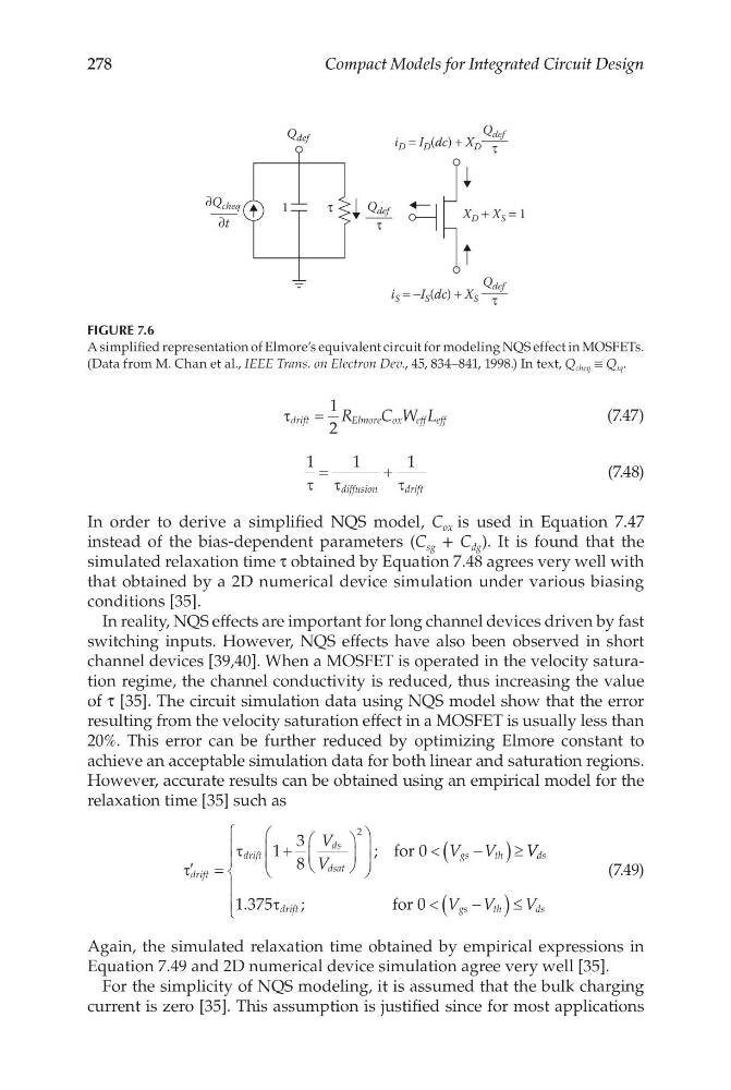
FIGURE 7.6
A simplified representation of Elmore’s equivalent circuit for modeling NQS effect in MOSFETs.
(Data from M. Chan et al., IEEE Trans. on Electron Dev., 45, 834–841, 1998.) In text, Q cheq ≡ Q iq .
Compact Models for Integrated Circuit Design
τ drift
Elmore ox eff eff
R
C W L
=
1
2
(7.47)
1
1
1
τ τ
τ
=
+
diffusion
drift
(7.48)
In order to derive a simplified NQS model, C ox is used in Equation 7.47
instead of the bias-dependent parameters (C sg + C dg ). It is found that the
simulated relaxation time τ obtained by Equation 7.48 agrees very well with
that obtained by a 2D numerical device simulation under various biasing
conditions [35].
In reality, NQS effects are important for long channel devices driven by fast
switching inputs. However, NQS effects have also been observed in short
channel devices [39,40]. When a MOSFET is operated in the velocity saturation regime, the channel conductivity is reduced, thus increasing the value
of τ [35]. The circuit simulation data using NQS model show that the error
resulting from the velocity saturation effect in a MOSFET is usually less than
20%. This error can be further reduced by optimizing Elmore constant to
achieve an acceptable simulation data for both linear and saturation regions.
However, accurate results can be obtained using an empirical model for the
relaxation time [35] such as
′ =
+
<
−
(
) ≥
τ
τ
drift
drift
ds
dsat
gs
th
V
V
V V
1
3
8
2
; for 0
V V
V V
V
ds
drift
gs
th
ds
1 375
.
;
τ
for 0 <
−
(
) ≤
(7.49)
Again, the simulated relaxation time obtained by empirical expressions in
Equation 7.49 and 2D numerical device simulation agree very well [35].
For the simplicity of NQS modeling, it is assumed that the bulk charging
current is zero [35]. This assumption is justified since for most applications
Q def
i D = I D (dc) + X D
X D + X S = 1
1
τ
Q def
τ
Q def
τ
i S = −I S (dc) + X S
Q def
τ
∂Q cheq
∂t
FIGURE 7.6
A simplified representation of Elmore’s equivalent circuit for modeling NQS effect in MOSFETs.
(Data from M. Chan et al., IEEE Trans. on Electron Dev., 45, 834–841, 1998.) In text, Q cheq ≡ Q iq .