

247
MOSFET Capacitance Models
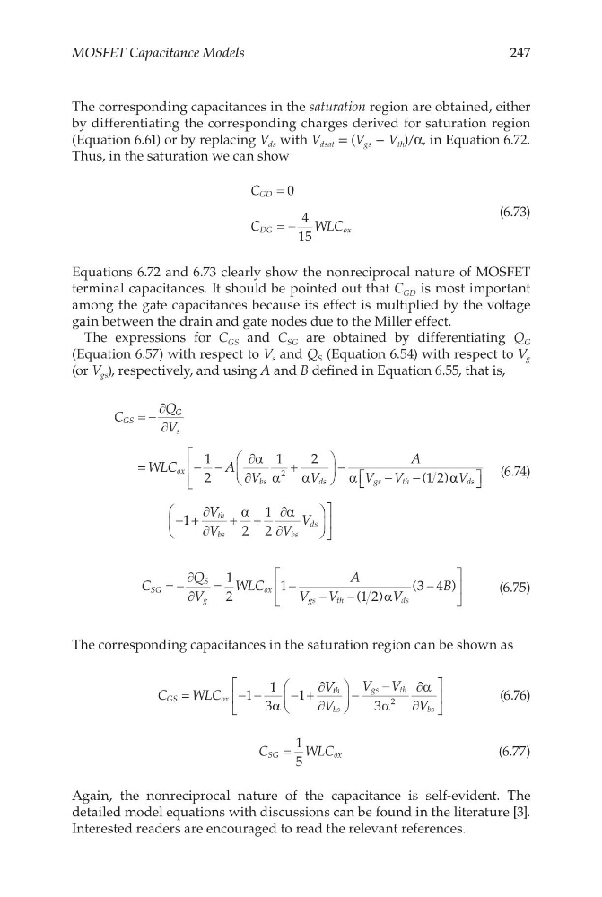
The corresponding capacitances in the saturation region are obtained, either
by differentiating the corresponding charges derived for saturation region
(Equation 6.61) or by replacing V ds with V dsat = (V gs − V th )/α, in Equation 6.72.
Thus, in the saturation we can show
C
C
W LC
GD
DG
ox
=
= −
0
4
15
(6.73)
Equations 6.72 and 6.73 clearly show the nonreciprocal nature of MOSFET
terminal capacitances. It should be pointed out that C GD is most important
among the gate capacitances because its effect is multiplied by the voltage
gain between the drain and gate nodes due to the Miller effect.
The expressions for C GS and C SG are obtained by differentiating Q G
(Equation 6.57) with respect to V s and Q S (Equation 6.54) with respect to V g
(or V gs ), respectively, and using A and B defined in Equation 6.55, that is,
C
Q
V
WLC
A V
V
A
V V
GS
G
s
ox
bs
ds
gs
th
= −
∂
∂
=
− −
∂
∂
+
−
−
−
1
2
1
2
1 2
2
α
α
α
α
( )α α
α
α
V
V
V
V
V
ds
th
bs
bs
ds
− +
∂
∂
+ +
∂
∂
1
2
1
2
(6.74)
C
Q
V
WLC
A
V V
V
B
SG
S
g
ox
gs
th
ds
= −
∂
∂
=
−
−
−
−
1
2
1
1 2
3 4
( )
(
)
α
(6.75)
The corresponding capacitances in the saturation region can be shown as
C
WLC
V
V
V V
V
GS
ox
th
bs
gs
th
bs
=
− −
− +
∂
∂
−
−
∂
∂
1
1
3
1
3
2
α
α
α
(6.76)
C
WLC
SG
ox
=
1
5
(6.77)
Again, the nonreciprocal nature of the capacitance is self-evident. The
detailed model equations with discussions can be found in the literature [3].
Interested readers are encouraged to read the relevant references.
MOSFET Capacitance Models
The corresponding capacitances in the saturation region are obtained, either
by differentiating the corresponding charges derived for saturation region
(Equation 6.61) or by replacing V ds with V dsat = (V gs − V th )/α, in Equation 6.72.
Thus, in the saturation we can show
C
C
W LC
GD
DG
ox
=
= −
0
4
15
(6.73)
Equations 6.72 and 6.73 clearly show the nonreciprocal nature of MOSFET
terminal capacitances. It should be pointed out that C GD is most important
among the gate capacitances because its effect is multiplied by the voltage
gain between the drain and gate nodes due to the Miller effect.
The expressions for C GS and C SG are obtained by differentiating Q G
(Equation 6.57) with respect to V s and Q S (Equation 6.54) with respect to V g
(or V gs ), respectively, and using A and B defined in Equation 6.55, that is,
C
Q
V
WLC
A V
V
A
V V
GS
G
s
ox
bs
ds
gs
th
= −
∂
∂
=
− −
∂
∂
+
−
−
−
1
2
1
2
1 2
2
α
α
α
α
( )α α
α
α
V
V
V
V
V
ds
th
bs
bs
ds
− +
∂
∂
+ +
∂
∂
1
2
1
2
(6.74)
C
Q
V
WLC
A
V V
V
B
SG
S
g
ox
gs
th
ds
= −
∂
∂
=
−
−
−
−
1
2
1
1 2
3 4
( )
(
)
α
(6.75)
The corresponding capacitances in the saturation region can be shown as
C
WLC
V
V
V V
V
GS
ox
th
bs
gs
th
bs
=
− −
− +
∂
∂
−
−
∂
∂
1
1
3
1
3
2
α
α
α
(6.76)
C
WLC
SG
ox
=
1
5
(6.77)
Again, the nonreciprocal nature of the capacitance is self-evident. The
detailed model equations with discussions can be found in the literature [3].
Interested readers are encouraged to read the relevant references.