

244
Compact Models for Integrated Circuit Design
expressions for terminal charges in the linear region. Thus, the expressions
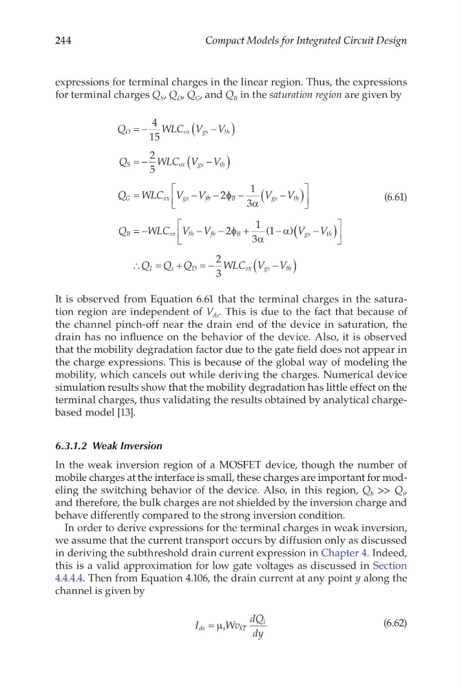
for terminal charges Q S , Q D , Q G , and Q B in the saturation region are given by
Q
W LC V V
Q
WLC V V
Q WLC V V
D
o x
g s
t h
S
o x
g s
t h
G
o x
g s
f b
= −
−
(
)
= −
−
(
)
=
−
−
4
15
2
5
2φ φ
α
φ
α
α
B
g s
t h
B
o x
t h
f b
B
gs
th
V V
Q
WLC V V
V V
−
−
(
)
= −
−
−
+
−
−
1
3
2
1
3
1
(
) ( (
)
∴ = +
=−
−
(
)
Q Q Q
W LC V V
I
s
D
o x
g s
t h
2
3
(6.61)
It is observed from Equation 6.61 that the terminal charges in the saturation region are independent of V ds . This is due to the fact that because of
the channel pinch-off near the drain end of the device in saturation, the
drain has no influence on the behavior of the device. Also, it is observed
that the mobility degradation factor due to the gate field does not appear in
the charge expressions. This is because of the global way of modeling the
mobility, which cancels out while deriving the charges. Numerical device
simulation results show that the mobility degradation has little effect on the
terminal charges, thus validating the results obtained by analytical chargebased model [13].
6.3.1.2 Weak Inversion
In the weak inversion region of a MOSFET device, though the number of
mobile charges at the interface is small, these charges are important for modeling the switching behavior of the device. Also, in this region, Q b >> Q i ,
and therefore, the bulk charges are not shielded by the inversion charge and
behave differently compared to the strong inversion condition.
In order to derive expressions for the terminal charges in weak inversion,
we assume that the current transport occurs by diffusion only as discussed
in deriving the subthreshold drain current expression in Chapter 4. Indeed,
this is a valid approximation for low gate voltages as discussed in Section
4.4.4.4. Then from Equation 4.106, the drain current at any point y along the
channel is given by
I
Wv
dQ
dy
ds
s
k T
i
= µ
(6.62)
Compact Models for Integrated Circuit Design
expressions for terminal charges in the linear region. Thus, the expressions
for terminal charges Q S , Q D , Q G , and Q B in the saturation region are given by
Q
W LC V V
Q
WLC V V
Q WLC V V
D
o x
g s
t h
S
o x
g s
t h
G
o x
g s
f b
= −
−
(
)
= −
−
(
)
=
−
−
4
15
2
5
2φ φ
α
φ
α
α
B
g s
t h
B
o x
t h
f b
B
gs
th
V V
Q
WLC V V
V V
−
−
(
)
= −
−
−
+
−
−
1
3
2
1
3
1
(
) ( (
)
∴ = +
=−
−
(
)
Q Q Q
W LC V V
I
s
D
o x
g s
t h
2
3
(6.61)
It is observed from Equation 6.61 that the terminal charges in the saturation region are independent of V ds . This is due to the fact that because of
the channel pinch-off near the drain end of the device in saturation, the
drain has no influence on the behavior of the device. Also, it is observed
that the mobility degradation factor due to the gate field does not appear in
the charge expressions. This is because of the global way of modeling the
mobility, which cancels out while deriving the charges. Numerical device
simulation results show that the mobility degradation has little effect on the
terminal charges, thus validating the results obtained by analytical chargebased model [13].
6.3.1.2 Weak Inversion
In the weak inversion region of a MOSFET device, though the number of
mobile charges at the interface is small, these charges are important for modeling the switching behavior of the device. Also, in this region, Q b >> Q i ,
and therefore, the bulk charges are not shielded by the inversion charge and
behave differently compared to the strong inversion condition.
In order to derive expressions for the terminal charges in weak inversion,
we assume that the current transport occurs by diffusion only as discussed
in deriving the subthreshold drain current expression in Chapter 4. Indeed,
this is a valid approximation for low gate voltages as discussed in Section
4.4.4.4. Then from Equation 4.106, the drain current at any point y along the
channel is given by
I
Wv
dQ
dy
ds
s
k T
i
= µ
(6.62)