

2
Compact Models for Integrated Circuit Design
with the parasitic elements of the active devices; and (2) compact interconnect
models of the resistors, capacitors, and inductors of the metallization layers
connecting the active devices in the ICs.
1.1.1 Compact Device Models
Compact device models describe the terminal behavior of a device in terms
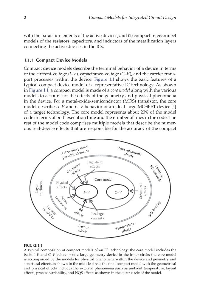
of the current-voltage (I–V), capacitance-voltage (C–V), and the carrier transport processes within the device. Figure 1.1 shows the basic features of a
typical compact device model of a representative IC technology. As shown
in Figure 1.1, a compact model is made of a core model along with the various
models to account for the effects of the geometry and physical phenomena
in the device. For a metal-oxide-semiconductor (MOS) transistor, the core
model describes I–V and C–V behavior of an ideal large MOSFET device [4]
of a target technology. The core model represents about 20% of the model
code in terms of both execution time and the number of lines in the code. The
rest of the model code comprises multiple models that describe the numerous real-device effects that are responsible for the accuracy of the compact
T e m p e ra tu re
e ff e c ts
S e l f - h e a t i n g
La yo ut
ef fe ct s
R F
e f f e c t s
S
e
r
i
e
s
r
e
s
i
s
t
a
n
c
e
s
Leakage
currents
G e o m e t r y
e f f e c t s
A c ti v e a n d p a ss iv e
p a ra si ti c e le m e n ts
Structural
effects
Layer
thickness
Core model
N o n -q u a si st at ic
ef fe c ts
Physical
effects
S
u
b
s
t
r
a
t
e
R
C
-
n
e
t
w
o
r
k
I–V
C –V
High-field
effects
P r o c e s s
v a r i a b i l i t y
FIGURE 1.1
A typical composition of compact models of an IC technology: the core model includes the
basic I–V and C–V behavior of a large geometry device in the inner circle; the core model
is accompanied by the models for physical phenomena within the device and geometry and
structural effects as shown in the middle circle; the final compact model with the geometrical
and physical effects includes the external phenomena such as ambient temperature, layout
effects, process variability, and NQS effects as shown in the outer circle of the model.
Compact Models for Integrated Circuit Design
with the parasitic elements of the active devices; and (2) compact interconnect
models of the resistors, capacitors, and inductors of the metallization layers
connecting the active devices in the ICs.
1.1.1 Compact Device Models
Compact device models describe the terminal behavior of a device in terms
of the current-voltage (I–V), capacitance-voltage (C–V), and the carrier transport processes within the device. Figure 1.1 shows the basic features of a
typical compact device model of a representative IC technology. As shown
in Figure 1.1, a compact model is made of a core model along with the various
models to account for the effects of the geometry and physical phenomena
in the device. For a metal-oxide-semiconductor (MOS) transistor, the core
model describes I–V and C–V behavior of an ideal large MOSFET device [4]
of a target technology. The core model represents about 20% of the model
code in terms of both execution time and the number of lines in the code. The
rest of the model code comprises multiple models that describe the numerous real-device effects that are responsible for the accuracy of the compact
T e m p e ra tu re
e ff e c ts
S e l f - h e a t i n g
La yo ut
ef fe ct s
R F
e f f e c t s
S
e
r
i
e
s
r
e
s
i
s
t
a
n
c
e
s
Leakage
currents
G e o m e t r y
e f f e c t s
A c ti v e a n d p a ss iv e
p a ra si ti c e le m e n ts
Structural
effects
Layer
thickness
Core model
N o n -q u a si st at ic
ef fe c ts
Physical
effects
S
u
b
s
t
r
a
t
e
R
C
-
n
e
t
w
o
r
k
I–V
C –V
High-field
effects
P r o c e s s
v a r i a b i l i t y
FIGURE 1.1
A typical composition of compact models of an IC technology: the core model includes the
basic I–V and C–V behavior of a large geometry device in the inner circle; the core model
is accompanied by the models for physical phenomena within the device and geometry and
structural effects as shown in the middle circle; the final compact model with the geometrical
and physical effects includes the external phenomena such as ambient temperature, layout
effects, process variability, and NQS effects as shown in the outer circle of the model.