

204
Compact Models for Integrated Circuit Design
used in describing bipolar junction transistor output resistance) and is
introduced for the analysis of the output resistance of MOSFET devices in
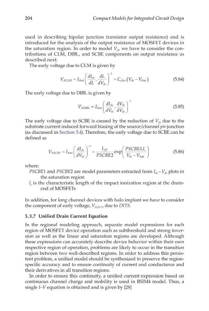
the saturation region. In order to model V A , we have to consider the contributions of CLM, DIBL, and SCBE components on output resistance as
described next:
The early voltage due to CLM is given by
V
I
dI
dL
dL
dV
C
V V
ACLM
dsat
ds
ds
clm
d s
d sat
=
=
−
(
)
−
.
.
1
(5.84)
The early voltage due to DIBL is given by
V
I
dI
dV
dV
dV
ADIBL
d sat
ds
th
th
ds
=
−
.
1
(5.85)
The early voltage due to SCBE is caused by the reduction of V th due to the
substrate current induced forward biasing of the source/channel pn-junction
(as discussed in Section 5.4). Therefore, the early voltage due to SCBE can be
defined as
V
I
dI
dV
L
PSCBE
PSCBE l
V V
ASCBE
d sat
ds
eff
c
ds
ds
=
=
−
−
ds
1
2
1
exp
.
a at
(5.86)
where:
PSCBE1 and PSCBE2 are model parameters extracted from I ds – V ds plots in
the saturation region
l c is the characteristic length of the impact ionization region at the drainend of MOSFETs
In addition, for long channel devices with halo implant we have to consider
the component of early voltage, V ADITS due to DITS.
5.3.7 Unified Drain Current Equation
In the regional modeling approach, separate model expressions for each
region of MOSFET device operation such as subthreshold and strong inversion as well as the linear and saturation regions are developed. Although
these expressions can accurately describe device behavior within their own
respective region of operation, problems are likely to occur in the transition
region between two well-described regions. In order to address this persistent problem, a unified model should be synthesized to preserve the regionspecific accuracy and to ensure continuity of current and conductance and
their derivatives in all transition regions.
In order to ensure this continuity, a unified current expression based on
continuous channel charge and mobility is used in BSIM4 model. Thus, a
single I–V equation is obtained and is given by [28]
Compact Models for Integrated Circuit Design
used in describing bipolar junction transistor output resistance) and is
introduced for the analysis of the output resistance of MOSFET devices in
the saturation region. In order to model V A , we have to consider the contributions of CLM, DIBL, and SCBE components on output resistance as
described next:
The early voltage due to CLM is given by
V
I
dI
dL
dL
dV
C
V V
ACLM
dsat
ds
ds
clm
d s
d sat
=
=
−
(
)
−
.
.
1
(5.84)
The early voltage due to DIBL is given by
V
I
dI
dV
dV
dV
ADIBL
d sat
ds
th
th
ds
=
−
.
1
(5.85)
The early voltage due to SCBE is caused by the reduction of V th due to the
substrate current induced forward biasing of the source/channel pn-junction
(as discussed in Section 5.4). Therefore, the early voltage due to SCBE can be
defined as
V
I
dI
dV
L
PSCBE
PSCBE l
V V
ASCBE
d sat
ds
eff
c
ds
ds
=
=
−
−
ds
1
2
1
exp
.
a at
(5.86)
where:
PSCBE1 and PSCBE2 are model parameters extracted from I ds – V ds plots in
the saturation region
l c is the characteristic length of the impact ionization region at the drainend of MOSFETs
In addition, for long channel devices with halo implant we have to consider
the component of early voltage, V ADITS due to DITS.
5.3.7 Unified Drain Current Equation
In the regional modeling approach, separate model expressions for each
region of MOSFET device operation such as subthreshold and strong inversion as well as the linear and saturation regions are developed. Although
these expressions can accurately describe device behavior within their own
respective region of operation, problems are likely to occur in the transition
region between two well-described regions. In order to address this persistent problem, a unified model should be synthesized to preserve the regionspecific accuracy and to ensure continuity of current and conductance and
their derivatives in all transition regions.
In order to ensure this continuity, a unified current expression based on
continuous channel charge and mobility is used in BSIM4 model. Thus, a
single I–V equation is obtained and is given by [28]