

200
Compact Models for Integrated Circuit Design
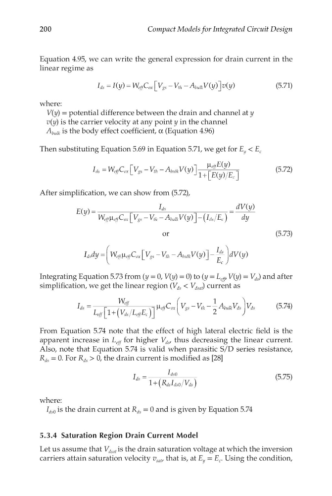
Equation 4.95, we can write the general expression for drain current in the
linear regime as
I
I y W C V V A V y v y
ds
eff ox
g s
t h
b ulk
=
=
−
−
( )
( ) ( )
(5.71)
where:
V(y) = potential difference between the drain and channel at y
v(y) is the carrier velocity at any point y in the channel
A bulk is the body effect coefficient, α (Equation 4.96)
Then substituting Equation 5.69 in Equation 5.71, we get for E y < E c
I
W C V V A V y
E y
E y E
ds
eff ox
g s
t h
b ulk
eff
c
=
−
−
+
( )
( )
( )
µ
1
(5.72)
After simplification, we can show from (5.72),
E y
I
W
C V V A V y
I E
dV y
dy
ds
eff eff ox
gs
th
bulk
ds
c
( )
( )
( )
=
−
−
− (
)
=
µ
or
I I dy W
C V V A V y
I
E
dV y
ds
eff eff ox
gs
th
bulk
ds
c
=
−
−
−
µ
( )
( )
(5.73)
Integrating Equation 5.73 from (y = 0, V(y) = 0) to (y = L eff , V(y) = V ds ) and after
simplification, we get the linear region (V ds < V dsat ) current as
I
W
L
V L E
C V V
A V
ds
eff
eff
d s
eff c
eff ox
g s
t h
b ulk ds
=
+ (
)
−
−
1
1
2
µ
V ds
(5.74)
From Equation 5.74 note that the effect of high lateral electric field is the
apparent increase in L eff for higher V ds , thus decreasing the linear current.
Also, note that Equation 5.74 is valid when parasitic S/D series resistance,
R ds = 0. For R ds > 0, the drain current is modified as [28]
I
I
R I V
ds
ds
ds ds
ds
= + (
)
0
0
1
(5.75)
where:
I ds0 is the drain current at R ds = 0 and is given by Equation 5.74
5.3.4 Saturation Region Drain Current Model
Let us assume that V dsat is the drain saturation voltage at which the inversion
carriers attain saturation velocity v sat , that is, at E y = E c . Using the condition,
Compact Models for Integrated Circuit Design
Equation 4.95, we can write the general expression for drain current in the
linear regime as
I
I y W C V V A V y v y
ds
eff ox
g s
t h
b ulk
=
=
−
−
( )
( ) ( )
(5.71)
where:
V(y) = potential difference between the drain and channel at y
v(y) is the carrier velocity at any point y in the channel
A bulk is the body effect coefficient, α (Equation 4.96)
Then substituting Equation 5.69 in Equation 5.71, we get for E y < E c
I
W C V V A V y
E y
E y E
ds
eff ox
g s
t h
b ulk
eff
c
=
−
−
+
( )
( )
( )
µ
1
(5.72)
After simplification, we can show from (5.72),
E y
I
W
C V V A V y
I E
dV y
dy
ds
eff eff ox
gs
th
bulk
ds
c
( )
( )
( )
=
−
−
− (
)
=
µ
or
I I dy W
C V V A V y
I
E
dV y
ds
eff eff ox
gs
th
bulk
ds
c
=
−
−
−
µ
( )
( )
(5.73)
Integrating Equation 5.73 from (y = 0, V(y) = 0) to (y = L eff , V(y) = V ds ) and after
simplification, we get the linear region (V ds < V dsat ) current as
I
W
L
V L E
C V V
A V
ds
eff
eff
d s
eff c
eff ox
g s
t h
b ulk ds
=
+ (
)
−
−
1
1
2
µ
V ds
(5.74)
From Equation 5.74 note that the effect of high lateral electric field is the
apparent increase in L eff for higher V ds , thus decreasing the linear current.
Also, note that Equation 5.74 is valid when parasitic S/D series resistance,
R ds = 0. For R ds > 0, the drain current is modified as [28]
I
I
R I V
ds
ds
ds ds
ds
= + (
)
0
0
1
(5.75)
where:
I ds0 is the drain current at R ds = 0 and is given by Equation 5.74
5.3.4 Saturation Region Drain Current Model
Let us assume that V dsat is the drain saturation voltage at which the inversion
carriers attain saturation velocity v sat , that is, at E y = E c . Using the condition,