

181
Compact Models for Small Geometry MOSFETs
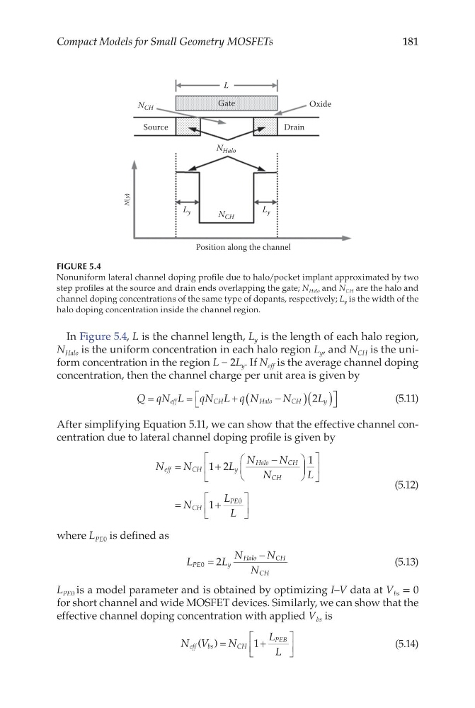
In Figure 5.4, L is the channel length, L y is the length of each halo region,
N Halo is the uniform concentration in each halo region L y , and N CH is the uniform concentration in the region L − 2L y . If N eff is the average channel doping
concentration, then the channel charge per unit area is given by
Q qN L qN L q N
N
L
eff
C H
H alo
C H
y
=
=
+
−
(
) ( )
2
(5.11)
After simplifying Equation 5.11, we can show that the effective channel concentration due to lateral channel doping profile is given by
N
N
L
N
N
N
L
N
L
L
eff
C H
y
Halo
CH
CH
CH
PE
=
+
−
=
+
1 2
1
1
0
(5.12)
where L PE0 is defined as
L
L
N
N
N
PE
y
Halo
CH
CH
0
2
=
−
(5.13)
L PE0 is a model parameter and is obtained by optimizing I–V data at V bs = 0
for short channel and wide MOSFET devices. Similarly, we can show that the
effective channel doping concentration with applied V bs is
N V
N
L
L
eff
bs
C H
PEB
( )=
+
1
(5.14)
Position along the channel
L y
L y
N CH
N Halo
Drain
Oxide
Gate
L
N CH
Source
N(y)
FIGURE 5.4
Nonuniform lateral channel doping profile due to halo/pocket implant approximated by two
step profiles at the source and drain ends overlapping the gate; N Halo and N CH are the halo and
channel doping concentrations of the same type of dopants, respectively; L y is the width of the
halo doping concentration inside the channel region.
Compact Models for Small Geometry MOSFETs
In Figure 5.4, L is the channel length, L y is the length of each halo region,
N Halo is the uniform concentration in each halo region L y , and N CH is the uniform concentration in the region L − 2L y . If N eff is the average channel doping
concentration, then the channel charge per unit area is given by
Q qN L qN L q N
N
L
eff
C H
H alo
C H
y
=
=
+
−
(
) ( )
2
(5.11)
After simplifying Equation 5.11, we can show that the effective channel concentration due to lateral channel doping profile is given by
N
N
L
N
N
N
L
N
L
L
eff
C H
y
Halo
CH
CH
CH
PE
=
+
−
=
+
1 2
1
1
0
(5.12)
where L PE0 is defined as
L
L
N
N
N
PE
y
Halo
CH
CH
0
2
=
−
(5.13)
L PE0 is a model parameter and is obtained by optimizing I–V data at V bs = 0
for short channel and wide MOSFET devices. Similarly, we can show that the
effective channel doping concentration with applied V bs is
N V
N
L
L
eff
bs
C H
PEB
( )=
+
1
(5.14)
Position along the channel
L y
L y
N CH
N Halo
Drain
Oxide
Gate
L
N CH
Source
N(y)
FIGURE 5.4
Nonuniform lateral channel doping profile due to halo/pocket implant approximated by two
step profiles at the source and drain ends overlapping the gate; N Halo and N CH are the halo and
channel doping concentrations of the same type of dopants, respectively; L y is the width of the
halo doping concentration inside the channel region.