

176
Compact Models for Integrated Circuit Design
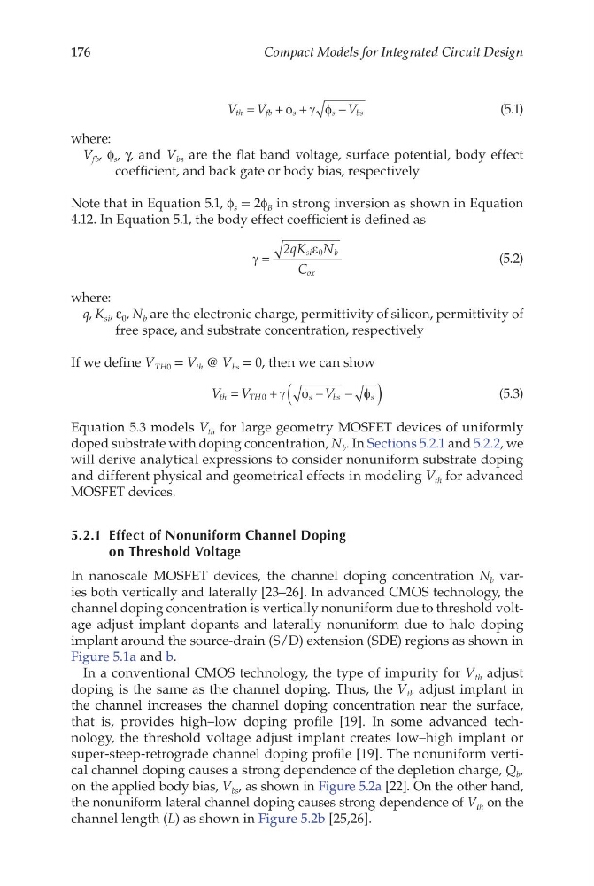
V V
V
th
fb
s
s
bs
=
+ +
−
φ γ φ
(5.1)
where:
V fb , f s , γ, and V bs are the flat band voltage, surface potential, body effect
coefficient, and back gate or body bias, respectively
Note that in Equation 5.1, f s = 2f B in strong inversion as shown in Equation
4.12. In Equation 5.1, the body effect coefficient is defined as
γ
ε
=
2
0
qK N
C
si
b
ox
(5.2)
where:
q, K si , ε 0 , N b are the electronic charge, permittivity of silicon, permittivity of
free space, and substrate concentration, respectively
If we define V TH0 = V th @ V bs = 0, then we can show
V V
V
th
TH
s
b s
s
=
+
−
−
(
)
0
γ φ
φ
(5.3)
Equation 5.3 models V th for large geometry MOSFET devices of uniformly
doped substrate with doping concentration, N b . In Sections 5.2.1 and 5.2.2, we
will derive analytical expressions to consider nonuniform substrate doping
and different physical and geometrical effects in modeling V th for advanced
MOSFET devices.
5.2.1 Effect of Nonuniform Channel Doping
on Threshold Voltage
In nanoscale MOSFET devices, the channel doping concentration N b varies both vertically and laterally [23–26]. In advanced CMOS technology, the
channel doping concentration is vertically nonuniform due to threshold voltage adjust implant dopants and laterally nonuniform due to halo doping
implant around the source-drain (S/D) extension (SDE) regions as shown in
Figure 5.1a and b.
In a conventional CMOS technology, the type of impurity for V th adjust
doping is the same as the channel doping. Thus, the V th adjust implant in
the channel increases the channel doping concentration near the surface,
that is, provides high–low doping profile [19]. In some advanced technology, the threshold voltage adjust implant creates low–high implant or
super- steep-retrograde channel doping profile [19]. The nonuniform vertical channel doping causes a strong dependence of the depletion charge, Q b ,
on the applied body bias, V bs , as shown in Figure 5.2a [22]. On the other hand,
the nonuniform lateral channel doping causes strong dependence of V th on the
channel length (L) as shown in Figure 5.2b [25,26].
Compact Models for Integrated Circuit Design
V V
V
th
fb
s
s
bs
=
+ +
−
φ γ φ
(5.1)
where:
V fb , f s , γ, and V bs are the flat band voltage, surface potential, body effect
coefficient, and back gate or body bias, respectively
Note that in Equation 5.1, f s = 2f B in strong inversion as shown in Equation
4.12. In Equation 5.1, the body effect coefficient is defined as
γ
ε
=
2
0
qK N
C
si
b
ox
(5.2)
where:
q, K si , ε 0 , N b are the electronic charge, permittivity of silicon, permittivity of
free space, and substrate concentration, respectively
If we define V TH0 = V th @ V bs = 0, then we can show
V V
V
th
TH
s
b s
s
=
+
−
−
(
)
0
γ φ
φ
(5.3)
Equation 5.3 models V th for large geometry MOSFET devices of uniformly
doped substrate with doping concentration, N b . In Sections 5.2.1 and 5.2.2, we
will derive analytical expressions to consider nonuniform substrate doping
and different physical and geometrical effects in modeling V th for advanced
MOSFET devices.
5.2.1 Effect of Nonuniform Channel Doping
on Threshold Voltage
In nanoscale MOSFET devices, the channel doping concentration N b varies both vertically and laterally [23–26]. In advanced CMOS technology, the
channel doping concentration is vertically nonuniform due to threshold voltage adjust implant dopants and laterally nonuniform due to halo doping
implant around the source-drain (S/D) extension (SDE) regions as shown in
Figure 5.1a and b.
In a conventional CMOS technology, the type of impurity for V th adjust
doping is the same as the channel doping. Thus, the V th adjust implant in
the channel increases the channel doping concentration near the surface,
that is, provides high–low doping profile [19]. In some advanced technology, the threshold voltage adjust implant creates low–high implant or
super- steep-retrograde channel doping profile [19]. The nonuniform vertical channel doping causes a strong dependence of the depletion charge, Q b ,
on the applied body bias, V bs , as shown in Figure 5.2a [22]. On the other hand,
the nonuniform lateral channel doping causes strong dependence of V th on the
channel length (L) as shown in Figure 5.2b [25,26].