

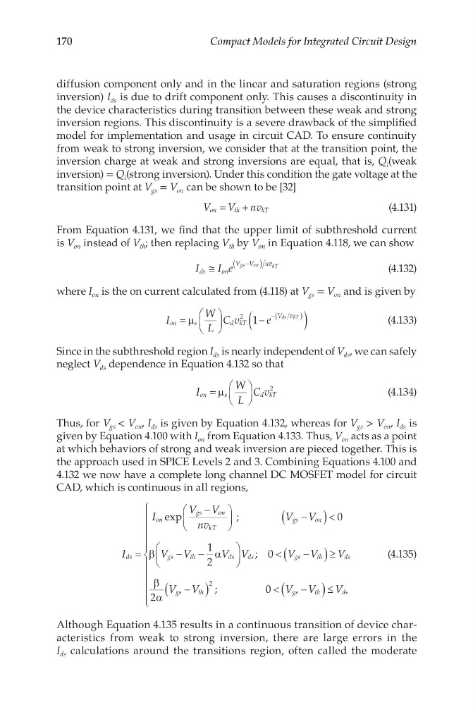
170
Compact Models for Integrated Circuit Design
diffusion component only and in the linear and saturation regions (strong
inversion) I ds is due to drift component only. This causes a discontinuity in
the device characteristics during transition between these weak and strong
inversion regions. This discontinuity is a severe drawback of the simplified
model for implementation and usage in circuit CAD. To ensure continuity
from weak to strong inversion, we consider that at the transition point, the
inversion charge at weak and strong inversions are equal, that is, Q i (weak
inversion) = Q i (strong inversion). Under this condition the gate voltage at the
transition point at V gs = V on can be shown to be [32]
V
V nv
on
th
kT
=
+
(4.131)
From Equation 4.131, we find that the upper limit of subthreshold current
is V on instead of V th ; then replacing V th by V on in Equation 4.118, we can show
I
I e
ds
on
V V
nv
gs
on
kT
≅
−
(
)
(4.132)
where I on is the on current calculated from (4.118) at V gs = V on and is given by
I
W
L
C v
e
on
s
dkT
V v
ds kT
=
−
(
)
−(
)
µ
2 1
(4.133)
Since in the subthreshold region I ds is nearly independent of V ds , we can safely
neglect V ds dependence in Equation 4.132 so that
I
W
L
C v
on
s
dkT
=
µ
2
(4.134)
Thus, for V gs < V on , I ds is given by Equation 4.132, whereas for V gs > V on , I ds is
given by Equation 4.100 with I on from Equation 4.133. Thus, V on acts as a point
at which behaviors of strong and weak inversion are pieced together. This is
the approach used in SPICE Levels 2 and 3. Combining Equations 4.100 and
4.132 we now have a complete long channel DC MOSFET model for circuit
CAD, which is continuous in all regions,
I
I
V V
nv
V V
V V
V
ds
on
gs
on
kT
gs
on
gs
th
ds
=
−
−
(
) <
−
−
;
exp
0
1
2
β
α
<
−
(
) ≥
−
(
)
<
−
(
) ≤
V
V V
V
V V
V V
V
ds
gs
th
ds
gs
th
gs
th
ds
;
;
0
2
0
2
β
α
(4.135)
Although Equation 4.135 results in a continuous transition of device characteristics from weak to strong inversion, there are large errors in the
I ds calculations around the transitions region, often called the moderate
Compact Models for Integrated Circuit Design
diffusion component only and in the linear and saturation regions (strong
inversion) I ds is due to drift component only. This causes a discontinuity in
the device characteristics during transition between these weak and strong
inversion regions. This discontinuity is a severe drawback of the simplified
model for implementation and usage in circuit CAD. To ensure continuity
from weak to strong inversion, we consider that at the transition point, the
inversion charge at weak and strong inversions are equal, that is, Q i (weak
inversion) = Q i (strong inversion). Under this condition the gate voltage at the
transition point at V gs = V on can be shown to be [32]
V
V nv
on
th
kT
=
+
(4.131)
From Equation 4.131, we find that the upper limit of subthreshold current
is V on instead of V th ; then replacing V th by V on in Equation 4.118, we can show
I
I e
ds
on
V V
nv
gs
on
kT
≅
−
(
)
(4.132)
where I on is the on current calculated from (4.118) at V gs = V on and is given by
I
W
L
C v
e
on
s
dkT
V v
ds kT
=
−
(
)
−(
)
µ
2 1
(4.133)
Since in the subthreshold region I ds is nearly independent of V ds , we can safely
neglect V ds dependence in Equation 4.132 so that
I
W
L
C v
on
s
dkT
=
µ
2
(4.134)
Thus, for V gs < V on , I ds is given by Equation 4.132, whereas for V gs > V on , I ds is
given by Equation 4.100 with I on from Equation 4.133. Thus, V on acts as a point
at which behaviors of strong and weak inversion are pieced together. This is
the approach used in SPICE Levels 2 and 3. Combining Equations 4.100 and
4.132 we now have a complete long channel DC MOSFET model for circuit
CAD, which is continuous in all regions,
I
I
V V
nv
V V
V V
V
ds
on
gs
on
kT
gs
on
gs
th
ds
=
−
−
(
) <
−
−
;
exp
0
1
2
β
α
<
−
(
) ≥
−
(
)
<
−
(
) ≤
V
V V
V
V V
V V
V
ds
gs
th
ds
gs
th
gs
th
ds
;
;
0
2
0
2
β
α
(4.135)
Although Equation 4.135 results in a continuous transition of device characteristics from weak to strong inversion, there are large errors in the
I ds calculations around the transitions region, often called the moderate