

166
Compact Models for Integrated Circuit Design
C
qK N
d
si
b
ss
=
ε
φ
0
2
(4.111)
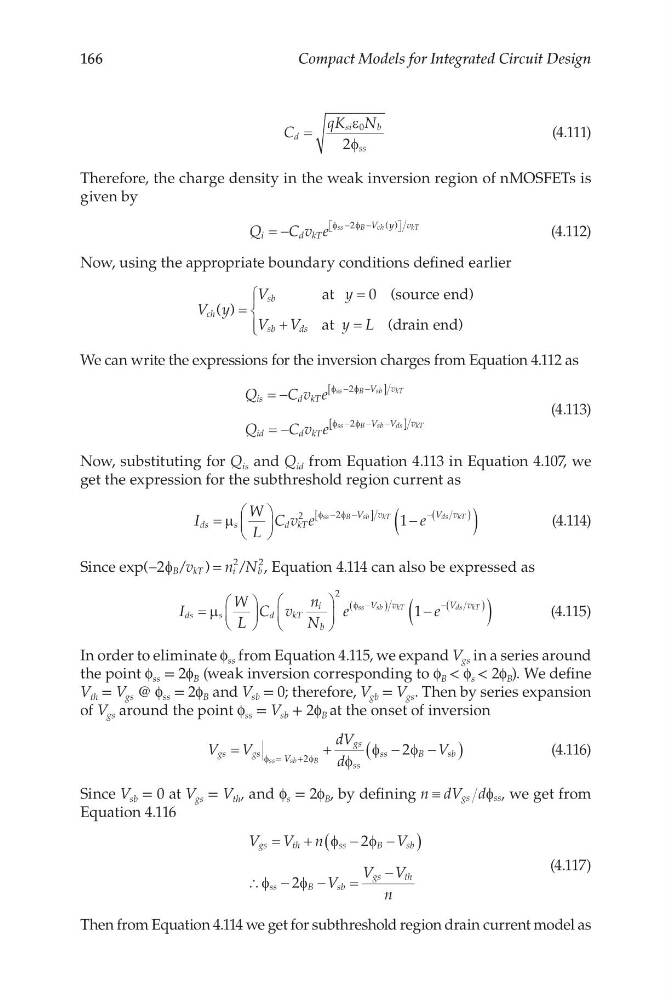
Therefore, the charge density in the weak inversion region of nMOSFETs is
given by
Q
C v e
i
d kT
V y v
ss
B
c h
k T
= −
−
−
φ
φ
2
( )
(4.112)
Now, using the appropriate boundary conditions defined earlier
V y
V
y
V V
y L
ch
sb
sb
ds
( ) =
=
+
=
at
(source end)
at
(drain end)
0
We can write the expressions for the inversion charges from Equation 4.112 as
Q
C v e
Q
C v e
is
d kT
V v
id
d kT
V V
v
ss
B
s b
k T
ss
B
s b
d s
k T
= −
= −
−
−
[
]
−
− −
[
]
φ
φ
φ
φ
2
2
(4.113)
Now, substituting for Q is and Q id from Equation 4.113 in Equation 4.107, we
get the expression for the subthreshold region current as
I
W
L
C v e
e
ds
s
dkT
V v
V v
ss
B
s b
k T
ds kT
=
−
(
)
−
−
[
]
−(
)
µ
φ
φ
2
2
1
(4.114)
Since exp(
/ )
/
−
=
2
2
2
φ B kT
i
b
v
n N , Equation 4.114 can also be expressed as
I
W
L
C v
n
N
e
e
ds
s
d
kT
i
b
V
v
V v
ss
sb
kT
ds kT
=
−
(
)
−
(
)
−(
)
µ
φ
2
1
(4.115)
In order to eliminate f ss from Equation 4.115, we expand V gs in a series around
the point f ss = 2f B (weak inversion corresponding to f B < f s < 2f B ). We define
V th = V gs @ f ss = 2f B and V sb = 0; therefore, V gb = V gs . Then by series expansion
of V gs around the point f ss = V sb + 2f B at the onset of inversion
V
V
dV
d
V
gs
gs
V
gs
ss
ss
B
s b
ss
sb
B
=
+
−
−
(
)
=
+
φ
φ
φ
φ
φ
2
2
(4.116)
Since V sb = 0 at V gs = V th , and f s = 2f B , by defining n dV d
gs
ss
≡
φ , we get from
Equation 4.116
V
V n
V
V
V V
n
gs
th
ss
B
s b
ss
B
s b
gs
th
=
+
−
−
(
)
∴ −
−
=
−
φ
φ
φ
φ
2
2
(4.117)
Then from Equation 4.114 we get for subthreshold region drain current model as
Compact Models for Integrated Circuit Design
C
qK N
d
si
b
ss
=
ε
φ
0
2
(4.111)
Therefore, the charge density in the weak inversion region of nMOSFETs is
given by
Q
C v e
i
d kT
V y v
ss
B
c h
k T
= −
−
−
φ
φ
2
( )
(4.112)
Now, using the appropriate boundary conditions defined earlier
V y
V
y
V V
y L
ch
sb
sb
ds
( ) =
=
+
=
at
(source end)
at
(drain end)
0
We can write the expressions for the inversion charges from Equation 4.112 as
Q
C v e
Q
C v e
is
d kT
V v
id
d kT
V V
v
ss
B
s b
k T
ss
B
s b
d s
k T
= −
= −
−
−
[
]
−
− −
[
]
φ
φ
φ
φ
2
2
(4.113)
Now, substituting for Q is and Q id from Equation 4.113 in Equation 4.107, we
get the expression for the subthreshold region current as
I
W
L
C v e
e
ds
s
dkT
V v
V v
ss
B
s b
k T
ds kT
=
−
(
)
−
−
[
]
−(
)
µ
φ
φ
2
2
1
(4.114)
Since exp(
/ )
/
−
=
2
2
2
φ B kT
i
b
v
n N , Equation 4.114 can also be expressed as
I
W
L
C v
n
N
e
e
ds
s
d
kT
i
b
V
v
V v
ss
sb
kT
ds kT
=
−
(
)
−
(
)
−(
)
µ
φ
2
1
(4.115)
In order to eliminate f ss from Equation 4.115, we expand V gs in a series around
the point f ss = 2f B (weak inversion corresponding to f B < f s < 2f B ). We define
V th = V gs @ f ss = 2f B and V sb = 0; therefore, V gb = V gs . Then by series expansion
of V gs around the point f ss = V sb + 2f B at the onset of inversion
V
V
dV
d
V
gs
gs
V
gs
ss
ss
B
s b
ss
sb
B
=
+
−
−
(
)
=
+
φ
φ
φ
φ
φ
2
2
(4.116)
Since V sb = 0 at V gs = V th , and f s = 2f B , by defining n dV d
gs
ss
≡
φ , we get from
Equation 4.116
V
V n
V
V
V V
n
gs
th
ss
B
s b
ss
B
s b
gs
th
=
+
−
−
(
)
∴ −
−
=
−
φ
φ
φ
φ
2
2
(4.117)
Then from Equation 4.114 we get for subthreshold region drain current model as