

144
Compact Models for Integrated Circuit Design
I
W
L
Q y dV
ds
s
i
ch
V
V V
sb
sb
ds
=
+
∫
µ
( )
(4.29)
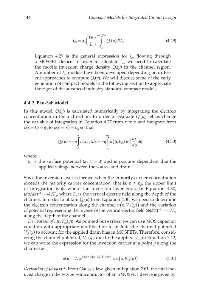
Equation 4.29 is the general expression for I ds flowing through
a MOSFET device. In order to calculate I ds , we need to calculate
the mobile inversion charge density Q i (y) in the channel region.
A number of I ds models have been developed depending on different approaches to compute Q i (y). We will discuss some of the early
generation of compact models in the following section to appreciate
the rigor of the advanced industry standard compact models.
4.4.2 Pao-Sah Model
In this model, Q i (y) is calculated numerically by integrating the electron
concentration in the x direction. In order to evaluate Q i (y), let us change
the variable of integration in Equation 4.27 from x to ϕ and integrate from
ϕ(x = 0) = ϕ s to ϕ(x = ∝) = ϕ B so that
Q y
q n x y dx
q n V y
dx
d
d
i
c h
s
B
( )
( , )
, ( )
= −
= −
(
)
∝
∫
∫
0
φ
φ
φ
φ
φ
(4.30)
where:
ϕ s is the surface potential (at x = 0) and is position dependent due the
applied voltage between the source and drain
Since the inversion layer is formed when the minority carrier concentration
exceeds the majority carrier concentration, that is, ϕ ≥ ϕ B , the upper limit
of integration is ϕ B where the inversion layer ends. In Equation 4.30,
(dϕ/dx) −1 = –1/E x , where E x is the vertical electric field along the depth of the
channel. In order to obtain Q i (y) from Equation 4.30, we need to determine
the electron concentration along the channel n V y
ch
φ, ( )
(
) and the variation
of potential representing the inverse of the vertical electric field (dϕ/dx) −1 = –1/E x
along the depth of the channel.
Derivation of n(ϕ,V ch (y)): As pointed out earlier, we can use MOS capacitor
equation with appropriate modification to include the channel potential
V ch (y) to account for the applied drain bias in MOSFETs. Therefore, considering the channel potential, V ch (y), due to the applied V ds in Equation 3.42,
we can write the expression for the inversion carrier at a point y along the
channel as
n y N e
n V y
b
y
V y v
ch
B
c h
k T
( )
, ( )
( )
( ) /
=
≡(
)
−
−
(
)
φ
φ
φ
2
(4.31)
Derivation of (dϕ/dx) −1 : From Gauss’s law given in Equation 2.61, the total induced charge in the ptype semiconductor of an nMOSFET device is given by
Compact Models for Integrated Circuit Design
I
W
L
Q y dV
ds
s
i
ch
V
V V
sb
sb
ds
=
+
∫
µ
( )
(4.29)
Equation 4.29 is the general expression for I ds flowing through
a MOSFET device. In order to calculate I ds , we need to calculate
the mobile inversion charge density Q i (y) in the channel region.
A number of I ds models have been developed depending on different approaches to compute Q i (y). We will discuss some of the early
generation of compact models in the following section to appreciate
the rigor of the advanced industry standard compact models.
4.4.2 Pao-Sah Model
In this model, Q i (y) is calculated numerically by integrating the electron
concentration in the x direction. In order to evaluate Q i (y), let us change
the variable of integration in Equation 4.27 from x to ϕ and integrate from
ϕ(x = 0) = ϕ s to ϕ(x = ∝) = ϕ B so that
Q y
q n x y dx
q n V y
dx
d
d
i
c h
s
B
( )
( , )
, ( )
= −
= −
(
)
∝
∫
∫
0
φ
φ
φ
φ
φ
(4.30)
where:
ϕ s is the surface potential (at x = 0) and is position dependent due the
applied voltage between the source and drain
Since the inversion layer is formed when the minority carrier concentration
exceeds the majority carrier concentration, that is, ϕ ≥ ϕ B , the upper limit
of integration is ϕ B where the inversion layer ends. In Equation 4.30,
(dϕ/dx) −1 = –1/E x , where E x is the vertical electric field along the depth of the
channel. In order to obtain Q i (y) from Equation 4.30, we need to determine
the electron concentration along the channel n V y
ch
φ, ( )
(
) and the variation
of potential representing the inverse of the vertical electric field (dϕ/dx) −1 = –1/E x
along the depth of the channel.
Derivation of n(ϕ,V ch (y)): As pointed out earlier, we can use MOS capacitor
equation with appropriate modification to include the channel potential
V ch (y) to account for the applied drain bias in MOSFETs. Therefore, considering the channel potential, V ch (y), due to the applied V ds in Equation 3.42,
we can write the expression for the inversion carrier at a point y along the
channel as
n y N e
n V y
b
y
V y v
ch
B
c h
k T
( )
, ( )
( )
( ) /
=
≡(
)
−
−
(
)
φ
φ
φ
2
(4.31)
Derivation of (dϕ/dx) −1 : From Gauss’s law given in Equation 2.61, the total induced charge in the ptype semiconductor of an nMOSFET device is given by