

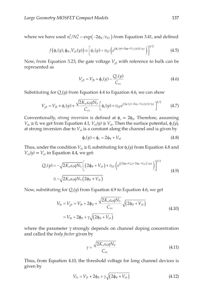
137
Large Geometry MOSFET Compact Models
where we have used n N
v
i
b
B
kT
2
2
2
/
exp
=
−
(
)
φ
from Equation 3.41, and defined
f
y
V y
y v e
s
B
ch
s
k T
y
V y v
s
B
ch
kT
φ
φ
φ
φ
φ
( ), , ( )
( )
( )
( ) /
(
) ≡
+
(
)
−
−
(
)
2
1 2
/
(4.5)
Now, from Equation 3.23, the gate voltage V gb with reference to bulk can be
represented as
V
V
y
Q y
C
gb
fb
s
s
ox
=
+
−
φ ( )
( )
(4.6)
Substituting for Q s (y) from Equation 4.4 to Equation 4.6, we can show
V
V
y
K qN
C
y v e
gb
fb
s
si
b
ox
s
k T
y
V y v
s
B
ch
k
=
+
+
+
−
−
(
)
φ
ε
φ
φ
φ
( )
( )
( ( )
() /
2
0
2
T T
1 2
/
(4.7)
Conventionally, strong inversion is defined at f s = 2f B . Therefore, assuming
V ds ≅ 0, we get from Equation 4.1, V ch (y) ≅ V sb . Then the surface potential, f s (y),
at strong inversion due to V sb is a constant along the channel and is given by
φ
φ
φ
s
s
B
s b
y
V
( ) = =
+
2
(4.8)
Thus, under the condition V ds ≅ 0, substituting for f s (y) from Equation 4.8 and
V ch (y) = V sb in Equation 4.4, we get:
Q y
K qN
V
v e
s
s i
b
B
s b
k T
V
V
v
B
s b
B
sb
kT
( )
/
= −
+
(
)+ (
)
+
(
) − −
(
)
2
2
0
2
2
ε
φ
φ
φ
≅ −
+
(
)
1 2
0
2
2
/
K qN
V
si
b
B
sb
ε
φ
(4.9)
Now, substituting for Q s (y) from Equation 4.9 to Equation 4.6, we get
V V
V
K qN
C
V
V
V
th
gb
fb
B
si
b
ox
B
s b
fb
B
B
sb
=
=
+
+
+
(
)
=
+
+
+
(
)
2
2
2
2
2
0
φ
ε
φ
φ γ
φ
(4.10)
where the parameter γ strongly depends on channel doping concentration
and called the body factor given by
γ
ε
=
2
0
K qN
C
si
b
ox
(4.11)
Thus, from Equation 4.10, the threshold voltage for long channel devices is
given by
V V
V
th
fb
B
B
sb
=
+
+
+
(
)
2
2
φ γ
φ
(4.12)
Large Geometry MOSFET Compact Models
where we have used n N
v
i
b
B
kT
2
2
2
/
exp
=
−
(
)
φ
from Equation 3.41, and defined
f
y
V y
y v e
s
B
ch
s
k T
y
V y v
s
B
ch
kT
φ
φ
φ
φ
φ
( ), , ( )
( )
( )
( ) /
(
) ≡
+
(
)
−
−
(
)
2
1 2
/
(4.5)
Now, from Equation 3.23, the gate voltage V gb with reference to bulk can be
represented as
V
V
y
Q y
C
gb
fb
s
s
ox
=
+
−
φ ( )
( )
(4.6)
Substituting for Q s (y) from Equation 4.4 to Equation 4.6, we can show
V
V
y
K qN
C
y v e
gb
fb
s
si
b
ox
s
k T
y
V y v
s
B
ch
k
=
+
+
+
−
−
(
)
φ
ε
φ
φ
φ
( )
( )
( ( )
() /
2
0
2
T T
1 2
/
(4.7)
Conventionally, strong inversion is defined at f s = 2f B . Therefore, assuming
V ds ≅ 0, we get from Equation 4.1, V ch (y) ≅ V sb . Then the surface potential, f s (y),
at strong inversion due to V sb is a constant along the channel and is given by
φ
φ
φ
s
s
B
s b
y
V
( ) = =
+
2
(4.8)
Thus, under the condition V ds ≅ 0, substituting for f s (y) from Equation 4.8 and
V ch (y) = V sb in Equation 4.4, we get:
Q y
K qN
V
v e
s
s i
b
B
s b
k T
V
V
v
B
s b
B
sb
kT
( )
/
= −
+
(
)+ (
)
+
(
) − −
(
)
2
2
0
2
2
ε
φ
φ
φ
≅ −
+
(
)
1 2
0
2
2
/
K qN
V
si
b
B
sb
ε
φ
(4.9)
Now, substituting for Q s (y) from Equation 4.9 to Equation 4.6, we get
V V
V
K qN
C
V
V
V
th
gb
fb
B
si
b
ox
B
s b
fb
B
B
sb
=
=
+
+
+
(
)
=
+
+
+
(
)
2
2
2
2
2
0
φ
ε
φ
φ γ
φ
(4.10)
where the parameter γ strongly depends on channel doping concentration
and called the body factor given by
γ
ε
=
2
0
K qN
C
si
b
ox
(4.11)
Thus, from Equation 4.10, the threshold voltage for long channel devices is
given by
V V
V
th
fb
B
B
sb
=
+
+
+
(
)
2
2
φ γ
φ
(4.12)