

544
Digital Electronics
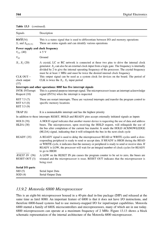
Table 13.3 (continued).
Signals
Description
IO/M(34)
This is a status signal that is used to differentiate between I/O and memory operations
S 1 and S 02933
These are status signals and can identify various operations
Power supply and clock frequency
V CC (40)
+ 5 V
V SS
Ground
X 1 X 2 (20)
A crystal, LC or RC network is connected at these two pins to drive the internal clock
generator. X 1 can also be an external clock input from a logic gate. The frequency is internally
divided by 2 to give the internal operating frequency of the processor. The crystal frequency
must be at least 1 MHz and must be twice the desired internal clock frequency
CLK OUT –
clock output
(37)
This output signal can be used as a system clock for devices on the board. The period of
CLK is twice the X 1 , X 2 input period
Interrupts and other operations: 8085 has five interrupt signals
INTR: INTerrupt
Request (10)
This is a general-purpose interrupt signal. The microprocessor issues an interrupt acknowledge
signal (INTA) when the interrupt is requested
RST 7.5 (7)
RST 6.5 (8)
RST 5.5 (9)
These are restart interrupts. These are vectored interrupts and transfer the program control to
specific memory locations
TRAP (6)
It is a nonmaskable interrupt and has the highest priority
In addition to these interrupts RESET, HOLD and READY pins accept externally initiated signals as inputs
HOLD (39)
HLDA (38)
A HOLD signal indicates that another master device is requesting the use of data and address
buses. The microprocessor, upon receiving the HOLD request, will relinquish the use of
the bus after completion of the current bus transfer. It sends the HOLD ACKNOWLEDGE
(HLDA) signal, indicating that it will relinquish the bus in the next clock cycle
READY (35)
A READY signal is used to delay the microprocessor READ or WRITE cycles until a slowresponding peripheral is ready to send or accept data. If READY is HIGH during the READ
or WRITE cycle, it indicates that the memory or peripheral is ready to send or receive data. If
READY is LOW, the processor will wait for an integral number of clock cycles for READY
to go to HIGH
RSEST IN (36)
RESET OUT (3)
A LOW on the RESET IN pin causes the program counter to be set to zero, the buses are
tristated and the microprocessor is reset. RESET OUT indicates that the microprocessor is
being reset
Serial I/O parts
SID (5)
Serial Input Data
SOD (4)
Serial Output Data
13.9.2 Motorola 6800 Microprocessor
This is an eight-bit microprocessor housed in a 40-pin dual in-line package (DIP) and released at the
same time as Intel 8080. An important feature of 6800 is that it does not have I/O instructions, and
therefore 6800-based systems had to use memory-mapped I/O for input/output capabilities. Motorola
6800 started a family of 680X microcontrollers and microprocessors, many of which are in use today.
6800 microprocessors can operate at a maximum frequency of 2 MHz. Figure 13.13 shows a block
schematic representation of the internal architecture of the Motorola 6800 microprocessor.
Digital Electronics
Table 13.3 (continued).
Signals
Description
IO/M(34)
This is a status signal that is used to differentiate between I/O and memory operations
S 1 and S 02933
These are status signals and can identify various operations
Power supply and clock frequency
V CC (40)
+ 5 V
V SS
Ground
X 1 X 2 (20)
A crystal, LC or RC network is connected at these two pins to drive the internal clock
generator. X 1 can also be an external clock input from a logic gate. The frequency is internally
divided by 2 to give the internal operating frequency of the processor. The crystal frequency
must be at least 1 MHz and must be twice the desired internal clock frequency
CLK OUT –
clock output
(37)
This output signal can be used as a system clock for devices on the board. The period of
CLK is twice the X 1 , X 2 input period
Interrupts and other operations: 8085 has five interrupt signals
INTR: INTerrupt
Request (10)
This is a general-purpose interrupt signal. The microprocessor issues an interrupt acknowledge
signal (INTA) when the interrupt is requested
RST 7.5 (7)
RST 6.5 (8)
RST 5.5 (9)
These are restart interrupts. These are vectored interrupts and transfer the program control to
specific memory locations
TRAP (6)
It is a nonmaskable interrupt and has the highest priority
In addition to these interrupts RESET, HOLD and READY pins accept externally initiated signals as inputs
HOLD (39)
HLDA (38)
A HOLD signal indicates that another master device is requesting the use of data and address
buses. The microprocessor, upon receiving the HOLD request, will relinquish the use of
the bus after completion of the current bus transfer. It sends the HOLD ACKNOWLEDGE
(HLDA) signal, indicating that it will relinquish the bus in the next clock cycle
READY (35)
A READY signal is used to delay the microprocessor READ or WRITE cycles until a slowresponding peripheral is ready to send or accept data. If READY is HIGH during the READ
or WRITE cycle, it indicates that the memory or peripheral is ready to send or receive data. If
READY is LOW, the processor will wait for an integral number of clock cycles for READY
to go to HIGH
RSEST IN (36)
RESET OUT (3)
A LOW on the RESET IN pin causes the program counter to be set to zero, the buses are
tristated and the microprocessor is reset. RESET OUT indicates that the microprocessor is
being reset
Serial I/O parts
SID (5)
Serial Input Data
SOD (4)
Serial Output Data
13.9.2 Motorola 6800 Microprocessor
This is an eight-bit microprocessor housed in a 40-pin dual in-line package (DIP) and released at the
same time as Intel 8080. An important feature of 6800 is that it does not have I/O instructions, and
therefore 6800-based systems had to use memory-mapped I/O for input/output capabilities. Motorola
6800 started a family of 680X microcontrollers and microprocessors, many of which are in use today.
6800 microprocessors can operate at a maximum frequency of 2 MHz. Figure 13.13 shows a block
schematic representation of the internal architecture of the Motorola 6800 microprocessor.