

526
Digital Electronics
Microprocessor
Address Bus
Data
bus
Control Bus
Memory
and
I/O
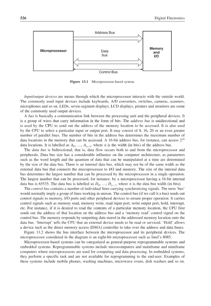
Figure 13.1 Microprocessor-based system.
Input/output devices are means through which the microprocessor interacts with the outside world.
The commonly used input devices include keyboards, A/D converters, switches, cameras, scanners,
microphones and so on. LEDs, seven-segment displays, LCD displays, printers and monitors are some
of the commonly used output devices.
A bus is basically a communication link between the processing unit and the peripheral devices. It
is a group of wires that carry information in the form of bits. The address bus is unidirectional and
is used by the CPU to send out the address of the memory location to be accessed. It is also used
by the CPU to select a particular input or output port. It may consist of 8, 16, 20 or an even greater
number of parallel lines. The number of bits in the address bus determines the maximum number of
data locations in the memory that can be accessed. A 16-bit address bus, for instance, can access 2
16
data locations. It is labelled as A 0 , …, A n−1 , where n is the width (in bits) of the address bus.
The data bus is bidirectional, that is, data flow occurs both to and from the microprocessor and
peripherals. Data bus size has a considerable influence on the computer architecture, as parameters
such as the word length and the quantum of data that can be manipulated at a time are determined
by the size of the data bus. There is an internal data bus, which may not be of the same width as the
external data bus that connects the microprocessor to I/O and memory. The size of the internal data
bus determines the largest number that can be processed by the microprocessor in a single operation.
The largest number that can be processed, for instance, by a microprocessor having a 16-bit internal
data bus is 65535. The data bus is labelled as D 0 , …, D n−1 , where n is the data bus width (in bits).
The control bus contains a number of individual lines carrying synchronizing signals. The term ‘bus’
would normally imply a group of lines working in unison. The control bus (if we call it a bus) sends out
control signals to memory, I/O ports and other peripheral devices to ensure proper operation. It carries
control signals such as memory read, memory write, read input port, write output port, hold, interrupt,
etc. For instance, if it is desired to read the contents of a particular memory location, the CPU first
sends out the address of that location on the address bus and a ‘memory read’ control signal on the
control bus. The memory responds by outputting data stored in the addressed memory location onto the
data bus. ‘Interrupt’ tells the CPU that an external device needs to be read or serviced. ‘Hold’ allows
a device such as the direct memory access (DMA) controller to take over the address and data buses.
Figure 13.2 shows the bus interface between the microprocessor and its peripheral devices. The
microprocessor considered in the diagram is an eight-bit microprocessor such as Intel’s 8085.
Microprocessor-based systems can be categorized as general-purpose reprogrammable systems and
embedded systems. Reprogrammable systems include microcomputers and mainframe and miniframe
computers where microprocessors are used for computing and data processing. In embedded systems,
they perform a specific task and are not available for reprogramming to the end-user. Examples of
these systems include mobile phones, washing machines, microwave ovens, dish washers and so on.
Digital Electronics
Microprocessor
Address Bus
Data
bus
Control Bus
Memory
and
I/O
Figure 13.1 Microprocessor-based system.
Input/output devices are means through which the microprocessor interacts with the outside world.
The commonly used input devices include keyboards, A/D converters, switches, cameras, scanners,
microphones and so on. LEDs, seven-segment displays, LCD displays, printers and monitors are some
of the commonly used output devices.
A bus is basically a communication link between the processing unit and the peripheral devices. It
is a group of wires that carry information in the form of bits. The address bus is unidirectional and
is used by the CPU to send out the address of the memory location to be accessed. It is also used
by the CPU to select a particular input or output port. It may consist of 8, 16, 20 or an even greater
number of parallel lines. The number of bits in the address bus determines the maximum number of
data locations in the memory that can be accessed. A 16-bit address bus, for instance, can access 2
16
data locations. It is labelled as A 0 , …, A n−1 , where n is the width (in bits) of the address bus.
The data bus is bidirectional, that is, data flow occurs both to and from the microprocessor and
peripherals. Data bus size has a considerable influence on the computer architecture, as parameters
such as the word length and the quantum of data that can be manipulated at a time are determined
by the size of the data bus. There is an internal data bus, which may not be of the same width as the
external data bus that connects the microprocessor to I/O and memory. The size of the internal data
bus determines the largest number that can be processed by the microprocessor in a single operation.
The largest number that can be processed, for instance, by a microprocessor having a 16-bit internal
data bus is 65535. The data bus is labelled as D 0 , …, D n−1 , where n is the data bus width (in bits).
The control bus contains a number of individual lines carrying synchronizing signals. The term ‘bus’
would normally imply a group of lines working in unison. The control bus (if we call it a bus) sends out
control signals to memory, I/O ports and other peripheral devices to ensure proper operation. It carries
control signals such as memory read, memory write, read input port, write output port, hold, interrupt,
etc. For instance, if it is desired to read the contents of a particular memory location, the CPU first
sends out the address of that location on the address bus and a ‘memory read’ control signal on the
control bus. The memory responds by outputting data stored in the addressed memory location onto the
data bus. ‘Interrupt’ tells the CPU that an external device needs to be read or serviced. ‘Hold’ allows
a device such as the direct memory access (DMA) controller to take over the address and data buses.
Figure 13.2 shows the bus interface between the microprocessor and its peripheral devices. The
microprocessor considered in the diagram is an eight-bit microprocessor such as Intel’s 8085.
Microprocessor-based systems can be categorized as general-purpose reprogrammable systems and
embedded systems. Reprogrammable systems include microcomputers and mainframe and miniframe
computers where microprocessors are used for computing and data processing. In embedded systems,
they perform a specific task and are not available for reprogramming to the end-user. Examples of
these systems include mobile phones, washing machines, microwave ovens, dish washers and so on.