

510
Digital Electronics
A/D
Converter
Analogue
IN
f s
Quantization
Noise
(a)
Digital filter
Removed Noise
(b)
Digital
Filter
A/D
Converter
Analogue
IN
fs/2
Kfs/2
Removed
Noise
(c)
Digital
Filter
Sigma-Delta
Modulator
Analogue
IN
Kfs
fs/2
Kfs/2
Kfs
f /2
s
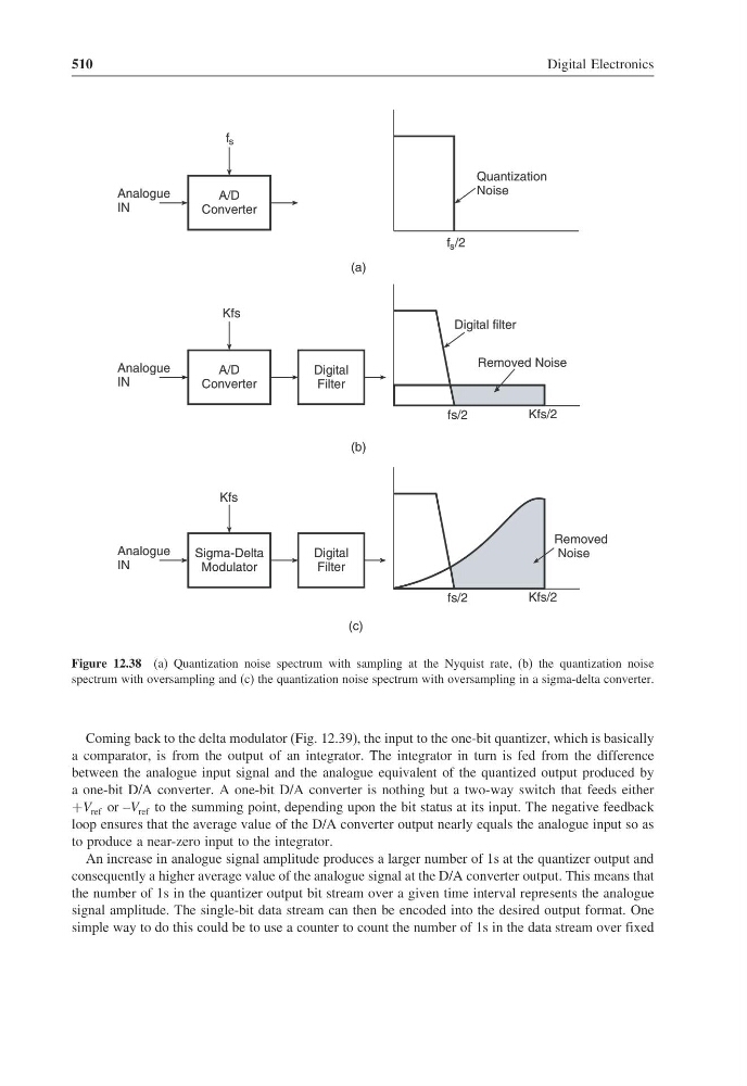
Figure 12.38 (a) Quantization noise spectrum with sampling at the Nyquist rate, (b) the quantization noise
spectrum with oversampling and (c) the quantization noise spectrum with oversampling in a sigma-delta converter.
Coming back to the delta modulator (Fig. 12.39), the input to the one-bit quantizer, which is basically
a comparator, is from the output of an integrator. The integrator in turn is fed from the difference
between the analogue input signal and the analogue equivalent of the quantized output produced by
a one-bit D/A converter. A one-bit D/A converter is nothing but a two-way switch that feeds either
+V ref or –V ref to the summing point, depending upon the bit status at its input. The negative feedback
loop ensures that the average value of the D/A converter output nearly equals the analogue input so as
to produce a near-zero input to the integrator.
An increase in analogue signal amplitude produces a larger number of 1s at the quantizer output and
consequently a higher average value of the analogue signal at the D/A converter output. This means that
the number of 1s in the quantizer output bit stream over a given time interval represents the analogue
signal amplitude. The single-bit data stream can then be encoded into the desired output format. One
simple way to do this could be to use a counter to count the number of 1s in the data stream over fixed
Digital Electronics
A/D
Converter
Analogue
IN
f s
Quantization
Noise
(a)
Digital filter
Removed Noise
(b)
Digital
Filter
A/D
Converter
Analogue
IN
fs/2
Kfs/2
Removed
Noise
(c)
Digital
Filter
Sigma-Delta
Modulator
Analogue
IN
Kfs
fs/2
Kfs/2
Kfs
f /2
s
Figure 12.38 (a) Quantization noise spectrum with sampling at the Nyquist rate, (b) the quantization noise
spectrum with oversampling and (c) the quantization noise spectrum with oversampling in a sigma-delta converter.
Coming back to the delta modulator (Fig. 12.39), the input to the one-bit quantizer, which is basically
a comparator, is from the output of an integrator. The integrator in turn is fed from the difference
between the analogue input signal and the analogue equivalent of the quantized output produced by
a one-bit D/A converter. A one-bit D/A converter is nothing but a two-way switch that feeds either
+V ref or –V ref to the summing point, depending upon the bit status at its input. The negative feedback
loop ensures that the average value of the D/A converter output nearly equals the analogue input so as
to produce a near-zero input to the integrator.
An increase in analogue signal amplitude produces a larger number of 1s at the quantizer output and
consequently a higher average value of the analogue signal at the D/A converter output. This means that
the number of 1s in the quantizer output bit stream over a given time interval represents the analogue
signal amplitude. The single-bit data stream can then be encoded into the desired output format. One
simple way to do this could be to use a counter to count the number of 1s in the data stream over fixed